Video Lecture
Theory For Making Notes
Force on conductor carrying current placed in a magnetic field.
Consider a straight conductor PQ of length l, area of cross-section A, carrying current `I’ placed in a uniform magnetic field of induction, \vec{B}. Let the conductor be placed along X-axis and magnetic field be acting in XY plane making an angle \theta with X-axis. Suppose the current I flows through the conductor from the end P to Q. Since the current in a conductor is due to motion of electrons, therefore, electrons are moving from the end Q to P (along its axis)
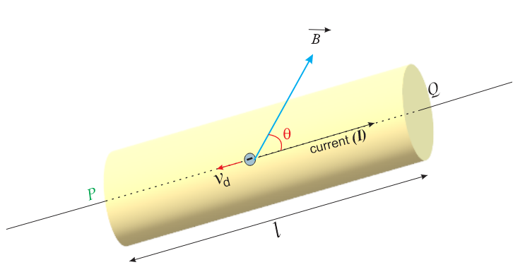
Let \displaystyle {{v}_{d}} be the drift velocity of electron and -e be the charge on each electron.
Then, magnetic Lorentz force on an electron is given by
\vec{f}=-e({{\vec{v}}_{d}}\times \vec{B})
If n is the number density of free electrons i.e., number of free electrons per unit volume of the conductor, then total number of free electrons in the conductor will be given by
N=n(Al)=nAl
Total force on the conductor is equal to the force acting on all the free electrons inside the conductor while moving in the magnetic field and is given by
\vec{F}=N\vec{f}=nAl[-e({{\vec{v}}_{d}}\times \vec{B})]
=-nAle({{\vec{v}}_{d}}\times \vec{B}) ——–(i)
We know that current through a conductor is related with drift velocity by the relation
I=nAe{{v}_{d}}
Or
Il=nAe{{v}_{d}}.l
We represent I\,\vec{l} as current element vector. It acts in the direction of flow of current . Since I\,\vec{l}and {{\vec{v}}_{d}} have opposite directions, hence in vector form we can write
I\,\vec{l}=-n\,Ale{{\vec{v}}_{d}} ———- (ii)
so eleminating \displaystyle {{v}_{d}} from equation (i) using equation (ii) we can find the relation for the force as given below
\displaystyle \vec{F}=I(\vec{l}\times \vec{B})
|\vec{F}|\,=\,I\,|\vec{l}\times \vec{B}|
hence magnitude of force is given by
F=I\,l\,\,B\sin \theta
where \theta is the smaller angle between I\,\,\vec{l} and \vec{B}.
Special Cases:
(a) If \theta {}^\circ or 180°, \sin \theta =0, from equation of force we have F=I\,lB(0)\,\,=0
It means a linear conductor carrying a current if be placed parallel to the direction of magnetic field, it experiences no force.
(b) If \theta =90{}^\circ ,\,\,\sin \theta =1; from equation of force we have F=I\,\,lB\times 1=I\,lB
It means a linear conductor carrying current if be placed perpendicular to the direction of magnetic field, it experiences maximum force.
Direction of force :
The direction of force is always perpendicular to the plane containing i\overrightarrow{{dl}} and \vec{B} and is same as that of the rule of cross-product of two vectors (\overrightarrow{A}\times \overrightarrow{B}).
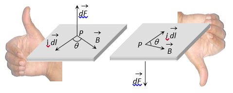
The direction of force when current element i\,\overrightarrow{{dl}} and \vec{B} are perpendicular to each other can also be determined by applying Fleming’s left hand rules.
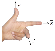
Fleming’s left-hand rule :
Stretch the fore-finger, central finger and thumb of left hand mutually perpendicular. Then if the fore-finger points in the direction of field \vec{B} and the central in the direction of current i, the thumb will point in the direction of force.
Force of Interaction Between Parallel Wires
The interaction between two parallel wires can be summarized as follows :
- Like currents attract while unlike currents repel each other.
- The force of interaction per unit length is proportional to the product of the currents in each wire.
- The force is inversely proportional to the distance between them.
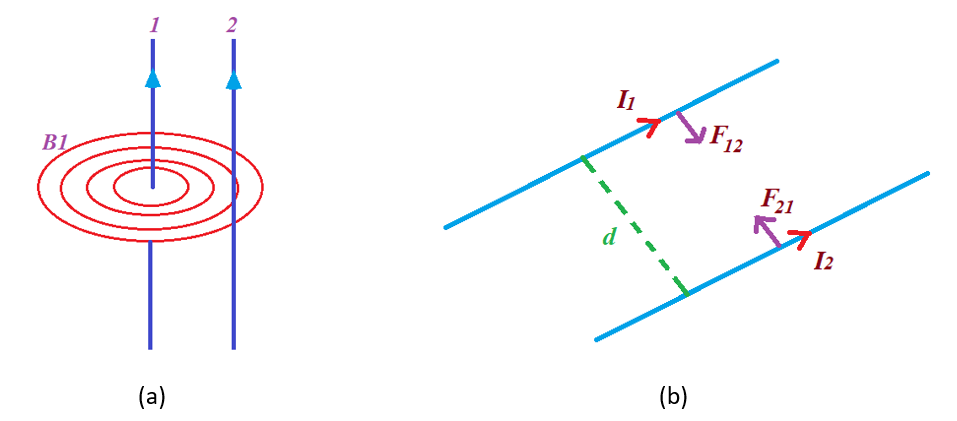
Figure (a) shows two parallel conductors carrying current. Each experience force due to the magnetic field of the other.
Figure (b) how that two conductors carrying current in the same direction feels attractive force towards each other
Consider two very long parallel wires carrying current I1 and I2 in the same direction as shown in the figure. The magnetic field produced by the current I1 at the position of I2 is given by
B1 = \frac{{{{\mu }_{o}}{{I}_{1}}}}{{2\pi d}}
Note that the direction of \vec{{B}_{1}}is perpendicular to wire 2. So the magnitude of force on wire 2 due to wire 1 is
\displaystyle {{\vec{F}}_{{21}}}={{I}_{2}}(\overrightarrow{{l}_{2}}\times {{\vec{B}}_{1}})
Þ \displaystyle {{F}_{{21}}}={{I}_{2}}{{l}_{2}}{{B}_{1}}\sin ({{90}^{o}})
or \displaystyle {{F}_{{21}}}={{I}_{2}}{{l}_{2}}\left( {\frac{{{{\mu }_{o}}{{I}_{1}}}}{{2\pi d}}} \right)
or \displaystyle {{F}_{{21}}}=\frac{{{{\mu }_{o}}{{I}_{1}}{{I}_{2}}}}{{2\pi d}}{{l}_{2}}
let f2 is the force per unit length then \displaystyle {{f}_{2}}=\frac{{{{F}_{{21}}}}}{{{{l}_{2}}}}
hence \displaystyle {{f}_{2}}=\frac{{{{F}_{{21}}}}}{{{{l}_{2}}}}=\frac{{{{\mu }_{o}}{{I}_{1}}{{I}_{2}}}}{{2\pi d}}
By applying the right hand rule one can note that the force is toward wire 1. The same analysis can be performed to find the force on the wire 1.
Hence if \displaystyle {{F}_{{12}}} is the force on first wire due to second. Then \displaystyle {{F}_{{12}}}=\frac{{{{\mu }_{o}}{{I}_{1}}{{I}_{2}}}}{{2\pi d}}{{l}_{1}}
let f1 is the force per unit length then \displaystyle {{f}_{1}}=\frac{{{{F}_{{12}}}}}{{{{l}_{2}}}}
hence \displaystyle {{f}_{1}}=\frac{{{{F}_{{12}}}}}{{{{l}_{2}}}}=\frac{{{{\mu }_{o}}{{I}_{1}}{{I}_{2}}}}{{2\pi d}}
Thus, the force of interaction per unit length between two parallel wires is same and is given by
f=\frac{{{{\mu }_{o}}{{I}_{1}}{{I}_{2}}}}{{2\pi d}}
Interaction between isolated current elements
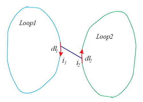
Let us consider two isolated current elements {{i}_{1}}d{{l}_{1}} and {{i}_{2}}d{{l}_{2}}. The magnetic field due to 1 at the site of 2 is given by Biot-Savart law is
d{{\vec{B}}_{{12}}}=\frac{{{{\mu }_{o}}}}{{4\pi }}\frac{{{{i}_{1}}d{{{\vec{l}}}_{1}}\times {{{\vec{r}}}_{{12}}}}}{{r_{{12}}^{3}}}
The force experienced by a current element in a magnetic field is given by Lorentz force d\vec{F}=id\vec{l}\times \vec{B}
Force experienced by 2 due to 1={{i}_{2}}d{{\vec{l}}_{2}}\times \frac{{{{\mu }_{o}}}}{{4\pi }}\frac{{{{i}_{1}}d{{{\vec{l}}}_{1}}\times {{{\vec{r}}}_{{12}}}}}{{r_{{12}}^{3}}}
d{{\vec{F}}_{{12}}}=\frac{{{{\mu }_{o}}}}{{4\pi }}{{i}_{1}}{{i}_{2}}\frac{{d{{{\vec{l}}}_{2}}\times (d{{{\vec{l}}}_{1}}\times {{{\vec{r}}}_{{12}}})}}{{r_{{12}}^{3}}}
Similarly d{{\vec{F}}_{{21}}}=\frac{{{{\mu }_{o}}}}{{4\pi }}{{i}_{1}}{{i}_{2}}\frac{{d{{{\vec{l}}}_{1}}\times (d{{{\vec{l}}}_{2}}\times {{{\vec{r}}}_{{21}}})}}{{r_{{21}}^{3}}}
In magnitude the forces can be written as
|d{{\vec{F}}_{{12}}}|\,\,\,=\frac{{{{\mu }_{o}}}}{{4\pi }}{{i}_{1}}{{i}_{2}}\frac{{|d{{{\vec{l}}}_{1}}|\,\,\,|d{{{\vec{l}}}_{2}}|}}{{r_{{21}}^{2}}}\cos {{\theta }_{2}}
and
|d{{\vec{F}}_{{21}}}|\,\,\,=\frac{{{{\mu }_{o}}}}{{4\pi }}{{i}_{1}}{{i}_{2}}\frac{{|d{{{\vec{l}}}_{1}}|\,\,\,|d{{{\vec{l}}}_{2}}|}}{{r_{{21}}^{2}}}\cos {{\theta }_{1}}
\displaystyle since\text{ }{{\theta }_{1}}\ne {{\theta }_{2}}
\displaystyle hence\text{ }|d{{\vec{F}}_{{12}}}|\ne d{{\vec{F}}_{{21}}}|
Thus we see that the forces are not equal and opposite. Hence there is apparent violation of the third law of motion. This does not mean that there is breakdown of Newton’s third law.
This apparent violation is due to acceleration and retardation of charge carriers at the ends of the elements. In the isolated elements charge carries are accelerated at the starting end from zero to a uniform velocity and at the other end from that uniform velocity to zero.
This acceleration and retardation produce and electromagnetic field, which carries away momentum from charge carriers, that is, charge carriers experience additional force. This force compounded with the above force shows that the force exerted by the elements are equal and opposite. So violation is only apparent. This situation arises only in case of isolated current element where there are acceleration and retardation of the charge carriers at the ends. In case of loops where there is no such acceleration or retardation of charge carriers there should be no violation of third law. In fact such difficulty does not arise. For loops shown in the figure here.
\displaystyle {{\vec{F}}_{{12}}}=\frac{{{{\mu }_{o}}}}{{4\pi }}{{i}_{1}}{{i}_{2}}\underset{{loop1}}{\mathop{\oint }}\,\text{ }\underset{{loop2}}{\mathop{\oint }}\,\frac{{d{{{\vec{l}}}_{2}}\times (d{{{\vec{l}}}_{1}}\times {{{\vec{r}}}_{{12}}})}}{{r_{{12}}^{2}}}
By mathematical laws this can be transformed into symmetrical from
\displaystyle {{\vec{F}}_{{12}}}=\frac{{{{\mu }_{o}}}}{{4\pi }}{{i}_{1}}{{i}_{2}}\underset{{Loop1}}{\mathop{\oint }}\,\text{ }\underset{{Loop2}}{\mathop{\oint }}\,\frac{{(d{{{\vec{l}}}_{1}}.d{{{\vec{l}}}_{2}}){{{\vec{r}}}_{{12}}}}}{{r_{{12}}^{2}}}
This equation shows that {{\vec{F}}_{{12}}}=-{{\vec{F}}_{{21}}}.
Comparison of Electrical and Magnetic Forces:
From coulomb’s law, the magnitude of electrostatic force between two charges {{q}_{1}} and {{q}_{2}} separated by distance r is given by
{{F}_{e}}=\frac{1}{{4\pi \,{{\in }_{o}}}}\,\frac{{{{q}_{1}}\,{{q}_{2}}}}{{{{r}^{2}}}}
Consider two parallel conducting wires of length d{{l}_{1}} and d{{l}_{2}} carrying currents {{I}_{1}} and {{I}_{2}} separated by distance r.
The magnitude of the magnetic force acting between these two current elements is given by
{{F}_{m}}=\frac{{{{\mu }_{o}}}}{{4\pi }}\frac{{{{I}_{1}}{{I}_{2}}}}{{{{r}^{2}}}}d{{l}_{1}}\,\,d{{l}_{2}}
Let {{q}_{1}} and {{q}_{2}} be the charges flowing for time t in wires for currents {{I}_{1}} and {{I}_{2}}. Then
{{I}_{1}}d{{l}_{1}}=\frac{{{{q}_{1}}}}{t}.\,d{{l}_{1}}={{q}_{1}}{{v}_{1}} and {{I}_{2}}d{{l}_{2}}=\frac{{{{q}_{2}}}}{t}\,\,\,\,\,d{{l}_{2}}\,={{q}_{2}}{{v}_{2}}
\therefore {{F}_{m}}=\frac{{{{\mu }_{o}}}}{{4\pi }}\,\,\frac{{{{q}_{1}}\,{{q}_{2}}}}{{{{r}^{2}}}}{{v}_{1}}{{v}_{2}}
Dividing the two forces we get \frac{{{{F}_{m}}}}{{{{F}_{e}}}}={{v}_{1}}{{v}_{2}}({{\mu }_{o}}{{\in }_{o}}).
Since left hand side in dimensionless, therefore, right hand side of must also be dimensionless. It means the quantity {{\mu }_{o}}{{\varepsilon }_{o}} must have the dimensions of {{\mathbf{(velocity)}}^{{-\mathbf{2}}}}. Here {{v}_{1}} and {{v}_{2}} are the drift velocities of electrons in current elements. As drift velocities are of the order of {{10}^{{-5}}}\,m{{s}^{{-1}}}, therefore
{{v}_{1}}{{v}_{2}}={{10}^{{-5}}}\times {{10}^{{-5}}}={{10}^{{-10}}}\,{{m}^{2}}{{s}^{{-2}}}
we also know that
{{c}^{2}}=\frac{1}{{{{\mu }_{o}}{{\in }_{o}}}} or {{\mu }_{o}}{{\in }_{o}}={{c}^{{-2}}}
where c is the velocity of light i.e. c=3\times {{10}^{8}}\,\,m{{s}^{{-1}}}
Putting values in \frac{{{{F}_{m}}}}{{{{F}_{e}}}}=\frac{{{{{10}}^{{-10}}}}}{{{{{(3\times {{{10}}^{8}})}}^{2}}}}\cong {{10}^{{-27}}}
It shows that the magnetic forces are very much smaller than the electrostatic forces in current carrying conductors. However, the electric forces never dominate the magnetic forces in current carrying conductors because
(i) the matter is electrically neutral to very high degree of accuracy. The flowing charges do not disturb the neutrality of the matter. Thus, the coloumb’s electric forces are very rarely in evidence.
(ii) in an electric current, the large number of electrons are drifting towards the same direction. This adds up weak magnetic fields, which become evident.
Note: If {{v}_{1}} and {{v}_{2}} are comparable to the speed of light, the magnetic and electric forces are comparable.
Practice Questions (Basic Level)
Q.1
A long vertical straight conductor (not shown) is placed at O in figure, carries an inward current of 5 A. A small straight wire X of length 0.03 m is placed along the tangent to the circle of centre O and radius 0.1m as shown. If X carries a current of 2A, the force on X in N is
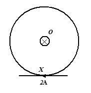
(a) 9 ´ 10-7 (b) 6 ´ 10-7 (c) zero (d) 3 ´ 10-7
Ans. (c)
Q.2
A long current-carrying wire W is free to move when placed in a magnetic field B at right angles to the field as shown

(a) it will move along the magnetic field to the right
(b) it will move upwards towards you
(c) it will move downwards away from you
(d) it will not move at all
Ans. (c)
Q.3
A rectangular loop carrying a current I is situated near a long straight wire such that the wire is parallel to one of the sides of loop. If a steady current I is established in the wire as shown in fig., the loop will
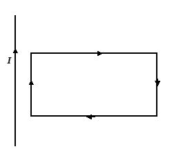
(a) rotate about an axis parallel to the wire
(b) move away from the wire
(c) move towards the wire
(d) remain stationary
Ans : (c)
Q.4
A circular coil of wire carries a current. PQ is part of a very long wire carrying a current and passing close to the circular coil. If the direction of the current are as shown in the figure. Then the direction of the force acting on PQ will be
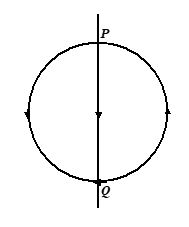
(a) parallel to PQ, towards P
(b) parallel to PQ, towards Q
(c) at right angles to PQ, to the right
(d) at right angles to PQ, to the left
Ans : (d)
Q.5
In the figure, X and Y are two long straight conductors each carrying a current of 2 A. The force on each conductor is F. When the current in each is changed to 1 A and reversed in direction, the force on each is now
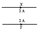
(a) F/4 and unchanged direction
(b) F/2 and reversed direction
(c) F/2 and unchanged direction
(d) F/4 and reversed direction
Ans. (a)
Q.6
P, Q and R are long parallel straight wires equally spaced in air, carrying current as shown in the figure. What is the direction of the resultant force on Q?
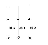
(a) to the left
(b) to the right
(c) perpendicular to plane of paper and direction inside
(d) perpendicular to plane of paper and direction upward
Ans : (b)
7.
A 3.0 cm wire carrying a current of 10A is placed inside a solenoid perpendicular to its axis. The magnetic field inside the solenoid is given to the 0.27 T. What is the magnetic force on the wire?find the force experienced by the conductor.
(a) 8.1\times {{10}^{{2}}}N
(b) 7.5\times {{10}^{{-2}}}N
(c) 8.1\times {{10}^{{5}}}N
(d) 8.1\times {{10}^{{-2}}}N
Ans (d)
8.
A conductor of length 20 cm is placed
(i)
parallel
(a)zero
(b)3
(c)9
(d)15
Ans (a)
(ii)
perpendicular
(a)0.8N
(b)0.2N
(c)1.0N
(d)2.5N
Ans (a)
(iii)
inclined at an angle 30°, to a uniform magnetic field of 2T. If the charge of 10 C passes through it in 5s.
(a)0.4N
(b)0.8N
(c)1.5N
(d) 2.0N
Ans (a)
9.
A long horizontal rigidly supported wire carries a current of 100A. Directly above it and parallel to it is a fine wire that carries a current of 200A and weighs 0.05 N/m. How far above the lower wire should the fire wire be kept to support it by magnetic repulsion?
(a)2 cm
(b) 4 cm
(c)6 cm
(d)8 cm
Ans (d)
10.
Find the magnetic force on segment PQ, due to a current of 5A flowing in it, if it is placed in a magnetic field of 0.25 T.
(a)0.20 N
(b)0.28 N
(c)0.35 N
(d)0.50 N
Ans (b)
11.
A current of 10A flows through each of two parallel long wires. The wires are 5 cm apart. Calculate the force acting per unit length of each wire. Use the standard value of constant required.
(a) 5\times {{10}^{{-4}}}N{{m}^{{-1}}}
(b) 9\times {{10}^{{-4}}}N{{m}^{{-1}}}
(c) 3\times {{10}^{{-4}}}N{{m}^{{-1}}}
(d) 4\times {{10}^{{-4}}}N{{m}^{{-1}}}
Ans(d)
12.
A short conductor of length 5.0 cm is placed parallel to a long conductor of length 1.5 cm near its center. The conductors carry currents 4.0 A and 3.0 A respectively in the same direction. What is the total force experienced by the ling conductor, when they are 3.0 cm apart?
(a) 2\times {{10}^{{-2}}}N
(b) 4\times {{10}^{{6}}}N
(c) 5\times {{10}^{{-6}}}N
(d) 4\times {{10}^{{-6}}}N
Ans (d)
13.
Two straight long parallel wires A and B carry currents of 5A and 10A respectively in opposite directions. The distance between the two wires is 0.1 m. Calculate the force on a 0.2 m section of the sire B near its center.
(a) 5\times {{10}^{{-5}}}\,N
(b) 2\times {{10}^{{5}}}\,N
(c) 2\times {{10}^{{-5}}}\,N
(d) 5\times {{10}^{{5}}}\,N
Ans (c)
Practice Questions (JEE Main Level)
Q.1
In figure shows three long straight wires P, Q and R carrying currents normal to the plane of the copper. All three currents have the same magnitude. Which arrow best shows the direction of the resultant force on the wire P?
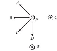
(a) A (b) B (c) C (d) D
Ans. (c)
Q.2
A horizontal power cable carries a constant current into the plane of the paper. Which arrow shows the direction of the force on the cable caused by the earth’s magnetic field in a region where the field is at 70° to the horizontal?
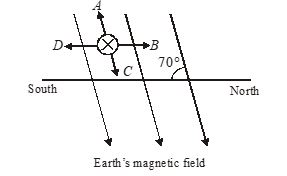
(a) A (b) B (c) C (d) D
Ans. (d)
Q.3
A conducting circular loop of radius r carries a constant current l. It is placed in uniform magnetic field B such that B is perpendicular to the plane of the loop. The net magnetic force acting on the loop is
(a) I\,r\,B
(b) 2\pi \,\,r\,IB
(c) Zero
(d) \pi \,\,r\,IB
Ans. (c)
Q.4
P, Q and R are long parallel straight wires in air, carrying currents as shown in figure. What is the direction of the resultant force on
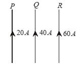
(a) To the left
(b) To the right
(c) Perpendicular to this page
(d) The same as that of the current in Q
Ans. (d)
Q.5
An irregular closed loop carrying a current has such a shape that the entire loop cannot lie in a single plane. If this loop is placed in a uniform magnetic field, the force acting on the loop
(a) Must be zero
(b) Can never be zero
(c) Can be zero only for one particular direction of the
(d) Cannot be ascertained
Ans. (a)
Q.6
As shown in figure a bar of mass m is suspended by two springs. A magnetic field B is directed out of the paper. Each spring has spring factor K. What is the description of motion of bar when a current I is sent through it in the direction shown
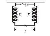
(a) The equilibrium is shifted upward by \frac{{BIL}}{{2k}}
(b) The equilibrium is shifted downward by \frac{{BIL}}{{2k}}
(c) The equilibrium is shifted downward by \frac{{BIl}}{{2(k+mg)}}
(d) The equilibrium is shifted upward by \frac{{BI\,l}}{{(2k+mg)}}
Ans. (a)
Q.7
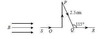
Find force on the segment CD as shown in figure, if B=0.15\,T and I=5\,A (\sin 65{}^\circ =0.9063)
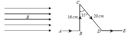
(a) Zero
(b) 0.12 N
(c) 0.13 N
(d) 0.14 N
Ans. (d)
Practice Questions (JEE Advance Level)
Q.1
A wire PQRS carrying a current I runs along three edges of a cube of side l as shown. There exists a uniform magnetic field of magnitude B along one of the sides of the cube. The magnitude of the force acting on the wire is
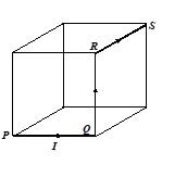
(a) zero (b) IlB (c) \sqrt{2}\,I\,lB (d) 2\,I\,lB
Ans : (c)