Video Lecture
Theory For Making Notes
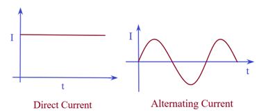
Electric Current
Charges in motion make an electric current.
Time rate of flow of charge through a cross-section is called electric current.
Suppose, a charge Δq passes through a given cross section Area in a short time Δt, then the average electric current is
Iav = \frac{{\Delta q}}{{\Delta t}}
More precisely, the instantaneous current at a given time t is
Iinst = \underset{{\Delta \,t\to 0}}{\mathop{{\lim }}}\,\frac{{\Delta q}}{{\Delta t}}=\frac{{dq}}{{dt}} \displaystyle n\ne 1
If the current is steady or constant (i.e., it does not change with time), then the charge q flowing through is a linear function of t (i.e. just proportional to tn, where n=1). In that case the average current and instantaneous current are same.
Whereas for a varying current where q= f(tn) where \displaystyle n\ne 1 the average current and the instantaneous currents may be different in magnitude.
Conventionally, the direction of current is taken to be the direction of flow of positive charge, (i.e., the direction of the field).Hence this current is also called conventional current. Whereas in a metallic conductor the actual current flows through the motion of electrons that takes place opposite to the motion of positive charges and this is called actual current.
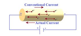
In a conductor (such as copper, aluminum, etc.) the current flows due to the motion of free electrons (negatively charged particles). Hence, the direction of electric current is opposite to the direction of flow of electrons.
In semiconductors, the current is carried by both the electrons (negative) and holes (positive). Hence, we say that in semiconductors there are two types of current carriers viz., electrons and holes. In a discharge tube, the current carriers are positive ions and negative electrons. In an electrolyte, the current flows due to the motion of both the positive ions and negative ions.
In case of semiconductors, electrolytes and discharge tubes, though the positive and the negative charge move in opposite directions, the current due to them will be in the same direction.
Furthermore, though the positive and negative charges are equal, their contributions to current are usually not the same. The heavier current -carriers move slower and their contribution to electric current is less than that of lighter ones.
Current Due to Translatory Motion of Charges
(i)
If n particles, each having a charge q, pass through a given area in time t, the current is given by
I = \frac{{\Delta Q}}{{\Delta t}}=\frac{{nq}}{t}
(ii)
If n particles, each having a charge q, pass per second per unit area, the current associated with cross-sectional area A is
I = \frac{{\Delta Q}}{{\Delta t}}=nqA
(iii)
If there are n particles per unit volume, each having a charge q and moving with velocity v, the current through cross-sectional area A is
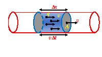
I = \frac{{\Delta Q}}{{\Delta t}}=nqA\frac{{\Delta x}}{{\Delta t}}=nqvA
Current Due to Rotatory Motion of Charge
If a point charge q is moving in a circle of radius r with speed v, then its time period T = (2πr/v).
So through a given cross-section (perpendicular to motion), the current is
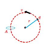
I=\frac{q}{t}=\frac{q}{T}=\frac{{qv}}{{2\pi r}}
Current Density
Electric current may be distributed non-uniformly over the surface through which it passes. Hence, in order to characterize the current in greater detail, we introduce the concept of current density vector \vec{J} at a point, defined as follows :
(1)
The magnitude of \vec{J} is equal to the current per unit area surrounding that point and normal to the direction of charge flow. Thus,
\left| {\vec{J}} \right|=\frac{{dI}}{{dA}}
(2)
The direction of \vec{J} is the same as the direction of velocity vector \displaystyle \vec{v} of the ordered motion of positive charge-carriers.
If the current is due to the motion of both positive and negative charges, the current density is given by
\vec{J} = {{\rho }_{+}}{{\vec{u}}_{+}}+{{\rho }_{-}}{{\vec{u}}_{-}}
where r+and r– are volume densities of positive and negative charge carriers, respectively, and {{\vec{u}}_{+}} and {{\vec{u}}_{-}} are their velocities.
In conductors, the charge is carried only by electrons. Therefore,
\vec{J} ={{\rho }_{-}}{{\vec{u}}_{-}}
Here, the value of ρ is negative. Hence the directions of \vec{J} and {{\vec{u}}_{-}} are opposite to each other.
If at point P current ΔI passes normally through area DAas shown. Current density \vec{J} at P is given by
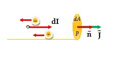
\vec{J}=\underset{{\Delta s\to 0}}{\mathop{{lim}}}\,\frac{{\Delta I}}{{\Delta A}}\vec{n}
or \vec{J}=\frac{{dI}}{{dA}}\vec{n}
In general, if the cross-sectional area dA is not normal to the current, then we take the projection of the area on a plane perpendicular to the direction of current.So the cross-sectional area normal to current will be dAcos θ and so in this situation,
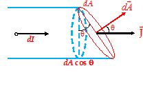
J=\frac{{dI}}{{dA\cos \theta }}
dI = JdA cos θ
or dI = \vec{J}.d\vec{A}
or I = \int{{\vec{J}.d\vec{A}}}
Thus, the electric current is the flux of current density.
Note the following important points about current density.
(1)
Both current I and current density \vec{J} have directions, by definition current density \vec{J} is a vector while current I is a scalar.
(2)
Though the charge density ρc is defined as charge per unit volume, it may have different values at different points, as
rc = \underset{{\Delta V\to 0}}{\mathop{{\lim }}}\,\frac{{\Delta q}}{{\Delta V}}
(3)
For uniform flow of charge through a cross-section normal to it, we have
I = nqvA
\vec{J} = \frac{I}{A}\vec{n}=\left( {nqv} \right)\vec{n} (as nv = ρc)
or \vec{J} = {{\rho }_{c}}\vec{v} = {{\rho }_{c}}\vec{v}
(4)
For a conductor, as we shall see
V = IR and R = \rho \frac{L}{A}
If E is the electric field, we have
V = IR
or EL = I \rho \frac{L}{A}
or J = \frac{I}{A}=\frac{1}{\rho }E
or \vec{J} = s \vec{E}
[As conductivity, s = \frac{1}{{resistivity,\,\,\rho }}]
Hence, in case of conductors, current density is proportional to electric field \vec{E} .
The above equation illustrates Ohm’s law in microscopic form. This in turn implies that
⇒ Direction of current density \vec{J} is same as that of electric field \vec{E}
⇒ If electric field is uniform (i.e., \vec{E}= constant) current density will be constant (as s = constant)
⇒ If electric field is zero (as in electrostatics, inside a conductor), current density and hence current will be zero.
⇒ For uniform current density \vec{J} across a normal cross-section \vec{S} , we have
I = \int{{\vec{J}.d\vec{A}}}
or I = \vec{J}.\vec{A} = JAcos 0o = JA [as \int{{d\vec{A}=\vec{A}}} and q = 0o)
This in turn implies that If the current is constant, J ∝ (1/A). Thus, for a given current, lesser the area, the greater will be the current density[Fig.(A)] and vice-versa
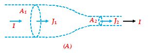
I = constant, i.e., J1A1 = J2A2
J2>J1 (as A2<A1)
If the current density is constant, I ∝ A. Thus, for a given current density, lesser the area of cross-section, the lesser will be the current. [Fig. (B)].
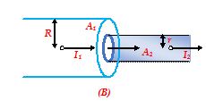
J = constant, i.e., (I1/A1) = (I2/A2)
I2<I1 (as A2<A1)
If the cross-section is constant, I ∝ J. Thus, for a given cross-sectional area, the greater the current density, the greater will be the current.
Drift Velocity
The drift velocity is the average uniform velocity acquired by free electrons inside a metal conductor by the application of an electric field which is responsible for current through it.
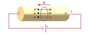
Free electrons, under the influence of thermal agitation, move randomly throughout the metallic conductor from one point to another in an irregular manner in all possible directions as shown in Fig. (A). However, if a source of potential difference is applied across the two ends of the conductor, the electrons gain velocities tending them to move from negative to positive side of the conductor. Average value of these velocities is termed as drift velocity. The drift velocity of the electrons is no doubt superimposed on their random velocity, but in fact this is the cause for net transportation of the charge along the conductor and hence results in a current flow.
In absence of any electric field the random motion of electrons does not contribute to any current. The number of electrons crossing any plane from left to right is equal to the number of electrons crossing from right to left (otherwise metal will not remain equipotential).
When an electric field is applied, due to electric force the path of electrons in general becomes curved instead of straight lines and electrons drift opposite to the field
Relation between drift velocity and electric field
Due to random motion, the free electrons of metal collide with positive metal ions and undergo change in direction after every collision. So, the thermal velocities are randomly distributed in all possible directions.Therefore, the average of all thermal velocities is zero
\vec{u}=\frac{{{{{\vec{u}}}_{1}}+{{{\vec{u}}}_{2}}+…..+{{{\vec{u}}}_{n}}}}{N}=zero
Here, {{\vec{u}}_{1}},\,{{\vec{u}}_{2}} , . . . , {{\vec{u}}_{n}} are the individual thermal velocities of the free electrons at any given time and N is the total number of free electrons in the conductor.
However, when some potential difference V is applied across the two ends of a conductor of length l, an electric field is set up. which is given by, E = V / l
then each free electron in the conductor experiences a force \displaystyle \vec{F}=-e\vec{E} in a direction opposite to the direction of electric field.
If m is the mass of the electron, then acceleration produced is \vec{a}=-\frac{{e\vec{E}}}{m}
At any given time, an electron has a velocity such that {{\vec{v}}_{1}}={{\vec{u}}_{1}}+\vec{a}{{\tau }_{1}} , where {{\vec{u}}_{1}} is the thermal velocity and \vec{a}{{\tau }_{1}} is the velocity acquired by the electron under the influence of the applied electric field. where t1 being the time of acceleration or time that has elapsed since the last collision.
Similarly, the velocities of the other electrons are {{\vec{v}}_{2}},\,{{\vec{v}}_{3}}…..{{\vec{v}}_{N}} , such that
{{\vec{v}}_{2}}={{\vec{u}}_{2}}+a{{\vec{\tau }}_{2}},
{{\vec{v}}_{3}}={{\vec{u}}_{3}}+\vec{a}{{\tau }_{3}}
,
.
.
.
{{\vec{v}}_{n}}={{\vec{u}}_{n}}+\vec{a}{{\tau }_{N}}
The average of all these velocities of all the free electrons in the conductor is the drift velocity .Drift velocity is defined as the velocity with which the free electrons get drifted towards the positive terminal under the influence of the externally applied electric field.
So, {{\vec{v}}_{d}}=\frac{{{{{\vec{v}}}_{1}}+{{{\vec{v}}}_{2}}+{{{\vec{v}}}_{3}}+…+{{{\vec{v}}}_{N}}}}{N}
\Rightarrow \text{ }{{\vec{v}}_{d}}=\frac{{({{{\vec{u}}}_{1}}+\vec{a}{{\tau }_{1}})+({{{\vec{u}}}_{2}}+\vec{a}{{\tau }_{2}})+….+({{{\vec{u}}}_{N}}+\vec{a}{{\tau }_{N}})}}{N}
\Rightarrow \text{ }{{\vec{v}}_{d}}=\frac{{({{{\vec{u}}}_{1}}+{{{\vec{u}}}_{2}}+….{{{\vec{u}}}_{N}})}}{N}+\vec{a}\left( {\frac{{{{\tau }_{1}}+{{\tau }_{2}}+….+{{\tau }_{N}}}}{N}} \right)
But, \frac{{{{{\vec{u}}}_{1}}+{{{\vec{u}}}_{2}}+…+{{{\vec{u}}}_{N}}}}{N}=0
⇒ {{\vec{v}}_{d}}=\vec{a}\frac{{{{\tau }_{1}}+{{\tau }_{2}}+….+{{\tau }_{N}}}}{N}
or, {{\vec{v}}_{d}}=\vec{a}\tau where \tau =\frac{{{{\tau }_{1}}+{{\tau }_{2}}+….+{{\tau }_{N}}}}{N}
Here, tis called the relaxation time and it is defined as the average time of acceleration between two successive collisions.
Now if we put \vec{a}=-\frac{{e\vec{E}}}{m}
we get {{\vec{v}}_{d}}=-\frac{{e\vec{E}}}{m}\tau
Current in a Conductor
Consider a conductor of uniform cross-sectional area S. If n is the number of free electrons per unit volume, the charge per unit volume is ne. If vdis the drift velocity, electrons move a distance vdin one second. Therefore, the volume moved in one second is vdS.
Thus, the current, \displaystyle I=\frac{{ch\arg edensity\times Volume}}{{Time}}=\frac{{(ne)\times (v{}_{d}A)}}{1}=nev{}_{d}A
J = \frac{I}{A}=ne{{v}_{d}}
or vd = \frac{J}{{ne}}
Metals (conductors) have large number of free electrons per unit volume (» 1028/m3). Therefore, the drift velocity is very small (»10-4 m/s) compared to random speed of electrons at room temperature (» 106 m/s).
Illustration
The area of cross-section, length and density of a piece of a metal of atomic mass 60 gm/mole are 10-6 m2, 1 m and 5 x 10³ kg/m3 respectively. Find the number of free electrons per unit volume if every atom contributes one free electron. Also find the drift velocity of electrons in the metal when a current of 16 A passes through it. Given that Avogadro’s number NA = 6 x 10²³/mole and charge on an electron e = 1.6 x 10⁻¹⁹ C.
Solution
According to Avogadro’s hypothesis,
\displaystyle \frac{N}{{{{N}_{A}}}}=\frac{m}{M}
so n = \displaystyle \frac{N}{V}={{N}_{A}}\frac{m}{{VM}}=\frac{{{{N}_{A}}d}}{M}
(as d = \displaystyle \frac{m}{V})
n = \displaystyle \frac{{6\times {{{10}}^{{23}}}\times \left( {5\times {{{10}}^{3}}} \right)}}{{\left( {60\times {{{10}}^{{-3}}}} \right)}} = 5 x 1028 /m3
Now as each atom contributes one electron, the number of electrons per unit volume is also the same.
J = \displaystyle \frac{I}{A}=\frac{{16}}{{{{{10}}^{{-6}}}}} = 16 x 106 A/m2
vd = \displaystyle \frac{J}{{ne}}=\frac{{16\times {{{10}}^{6}}}}{{\left( {5\times {{{10}}^{{28}}}} \right)\times \left( {1.6\times {{{10}}^{{-19}}}} \right)}}=2 x 10⁻³ m/s
Mobility (μ)
In a substance, although the amount of charge on a positive charge-carrier and on a negative charge–carrier may be the same, but the two types of carriers may not give equal contribution to electric current. For example, in a semiconductor, (such as Ge or Si), the two types of charge-carriers are electrons (negative) and holes (positive). When an electric field is applied, the electrons are found to drift more than the holes. We say that the mobility of electrons is more than that of holes.
Mobility (μ) of a charged particle in a substance is defined as the drift velocity per unit field applied,
m = \frac{{{{v}_{d}}}}{E}
The units of mobility are \frac{{m/\sec }}{{volt/m}} that is m2/Vs.
For a conductor we can write
J = nevd= neμE
An intrinsic semiconductor has same number of holes and electrons, and the amount of charge on them is also same. Hence
J = Current density due to drift of electrons + Current density due to drift of holes
= Je+ Jp = enμnE + epμpE (μn and μp are the mobility of negative and positive charge carriers)
J = en (μn + μp)E (as n = p)
Illustration
The current in a wire varies with time according to the relation
i = a + bt2,
where current i is in ampere and time t is in second; a = 4A, b = 2As-1.
(a)
How many coulomb pass a cross-section of the wire in the time interval between t = 5 s and
t = 10 s ?
(b)
What constant current could transport the same charge in same time interval ?
Solution
(a)
Δq = \displaystyle \int\limits_{5}^{{10}}{{i\,\,dt}}=\int\limits_{5}^{{10}}{{\left( {4+2{{t}^{2}}} \right)\,\,dt}}
= \displaystyle \left| {4t+\frac{2}{3}{{t}^{3}}} \right|_{5}^{{10}}=4\left( {10-5} \right)+\frac{2}{3}\left( {1000-125} \right) = 603.33 C
(b)
Ie = \displaystyle \frac{{\Delta q}}{{\Delta t}}=\frac{{603.33}}{{10-5}} = 120.67 A
Illustration
In the Bohr model of hydrogen atom, the electron is pictured to rotate in a circular orbit of radius 5´10-11 m, at a speed of 2.2 x 10⁶ m/s. What is the current associated with electron motion ?
Solution
The time taken to complete one rotation is
T = \frac{{2\pi r}}{v}
Therefore, the current is
I = \displaystyle \frac{q}{t}=\frac{e}{T}=\frac{{ev}}{{2\pi r}}=\frac{{1.6\times {{{10}}^{{-19}}}\times 2.2\times {{{10}}^{6}}}}{{2\times 3.14\times 5\times {{{10}}^{{-11}}}}} = 1.12 mA
Illustration
One end of the aluminium wire whose diameter is 2.5 mm is welded to one end of a copper wire whose diameter is 1.8mm. The composite wire carries a current I of 1.3A. What is the current density in each wire?
Solution
The current density is given by \displaystyle j=\frac{I}{A}
For Aluminium wire, \displaystyle {{A}_{{(AI)}}}=\frac{{\pi {{d}^{2}}}}{4}=\frac{\pi }{4}{{(2.5\times {{10}^{{-3}}})}^{2}}=4.91\times {{10}^{{-6}}}{{m}^{2}}
\displaystyle {{j}_{{(AI)}}}=\frac{I}{{{{A}_{{(AI)}}}}}=\frac{{1.3}}{{4.91\times {{{10}}^{{-6}}}}}=2.6\times {{10}^{5}}\text{A}{{\text{m}}^{{-2}}}=26A\,\text{c}{{\text{m}}^{{-2}}}
For copper wire, \displaystyle {{A}_{{\text{(Cu)}}}}=\frac{{\pi {{d}^{2}}}}{4}=\frac{\pi }{4}{{(1.8\times {{10}^{{-3}}})}^{2}}=2.54\times {{10}^{{-6}}}{{\text{m}}^{2}}
\displaystyle {{j}_{{\text{(Cu)}}}}=\frac{I}{{{{A}_{{\text{(Cu)}}}}}}=\frac{{1.3}}{{2.54\times {{{10}}^{{-6}}}}}=5.1\times {{10}^{5}}\text{A}{{\text{m}}^{{-2}}}=51A\,\,\text{c}{{\text{m}}^{{-2}}}
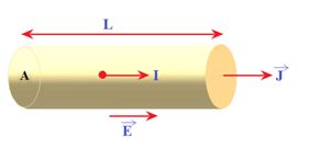
Ohm’s Law
Consider a conductor of cross section `A’. Let n be the free electron density in the conductor. And through a battery a current `I’ is made to flow in it.
We know that, I = neAvd and vd = \frac{{eE}}{m} t
\therefore \text{ }I=neA\left( {\frac{{eE}}{m}} \right)\tau
or, I=\frac{{n{{e}^{2}}AE}}{m}\tau (here E is electric field which is related to potential difference V)
we know that E=\frac{V}{L} , on putting it in the above relation of current we get
I=\left( {\frac{{n{{e}^{2}}A\tau }}{{mL}}} \right)V
Or V=\left( {\frac{{mL}}{{n{{e}^{2}}A\tau }}} \right)I
Now if we assume that in RHS all quantities written in the brackets are constant and denoting the whole bracket with a symbol `R’ then the above relation can be written as
V =RI ,(Ohm’s Law) where R=\frac{{mL}}{{n{{e}^{2}}A\tau }} and is called resistance.
Ohm’s Law
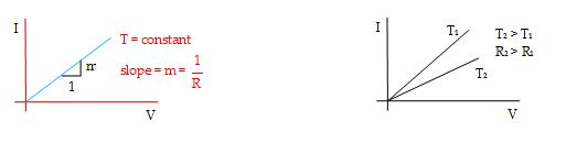
If the temperature of a conductor remains constant, then the ratio of the potential difference (or voltage) V to the current I remains constant for any conductor, which is known as resistance `R’ of the conductor.
\displaystyle \frac{V}{I} = constant = R
The graph showing the variation between current and voltage is shown in figure.
On the bases of Ohm’s Law the conductors are divided into two catagories
(i) Ohmic Conductors
(ii) Non Ohmic Conductors
Ohmic Conductors
The conductors which obey Ohm’s law are called Ohmic conductors. The resistance of an Ohmic conductor does not depend upon potential difference or current. Metallic conductors like copper, aluminum, iron etc. are the example of ohmic conductors. For such conductors the graph between current and voltage is always a straight line.
Non Ohmic Conductors
The conductors which do not obey ohm’s law are called non-Ohmic conductors. For such conductors, the graph between potential difference and current is not a straight line passing through the origin, e.g. vacuum tubes, semiconductors, etc.
Resistance
Resistance is the property of a substance by which it opposes the flow of current through it.
For a given body, the resistance is defined as the ratio of applied potential difference to the resulting current,
R = \frac{V}{I}
This property of the substance is due to frequent collisions of electrons with the atoms of the conductor.
SI unit of resistance is named ohm (W) which is equivalent to V/A. Its dimensions are
[R] = \left[ {\frac{V}{I}} \right]=\left[ {\frac{{Work/q}}{I}} \right]=\frac{{\left[ {M{{L}^{2}}{{T}^{{-2}}}/\left[ {AT} \right]} \right]}}{{\,\,\,\left[ A \right]}}=\left[ {M{{L}^{2}}{{T}^{{-3}}}{{A}^{{-2}}}} \right]
Reciprocal of the resistance is called conductance (G),
G = \frac{1}{R}=\frac{I}{V}
with dimensions [M-1L-2T3A2]. SI unit of conductance is called Siemens (S), which is equivalent to ohm-1.
Actually resistance R is given by the relation R=\frac{{mL}}{{n{{e}^{2}}A\tau }} as discussed earlier.
This can be written as R=\left( {\frac{m}{{n{{e}^{2}}\tau }}} \right)\frac{L}{A} . All quantities in the bracket are microscopic and together form a constant called resistivity denoted by symbol ρ.
Hence resistivity can be written as \displaystyle \rho =\frac{m}{{n{{e}^{2}}\tau }}.
Relation Between Resistance R and resistivity ρ
We know that R=\frac{{mL}}{{n{{e}^{2}}A\tau }}
or R=\left( {\frac{m}{{n{{e}^{2}}\tau }}} \right)\frac{L}{A} , but \frac{m}{{n{{e}^{2}}\tau }}=\rho
therefore
\displaystyle R=\rho \frac{L}{A}
To define the resistivity we take L=A=1 and put it in \displaystyle R=\rho \frac{L}{A}
so we get \displaystyle \rho =R
hence resistivity \displaystyle \rho is equal to the resistance of a conductor of unit length and area of cross section.
Since \rho =\frac{m}{{n{{e}^{2}}\tau }} It shows that resistivity depend only on two factors `n’ and `τ’ because m and e are constants
(i)
ρ ∝ \frac{1}{n} [where n = number of free electrons per unit volume which depends on the material of the conductor]
(ii)
ρ ∝ \frac{1}{\tau } [where t = average relaxation time of free electrons in the conductor.]
Variation of Resistivity with Temperature
ρ is independent of the shape and size of the conductor. It depends on temperature.
1.
In case of Ohmic conductors as temperature increases,ρ increases
Explanation
In case of conductors, the number of free electrons is fixed. Due to increase of temperature, the amplitude of vibration of atoms / ions increases. As a result of this, the collisions of electrons with the atoms become more effective and frequent. Therefore, τ decreases and hence ρ increases.
At any temperature t, r is given by the following linear relation with temperature
ρt = ρ0 (1 + αΔT),
where ρ0 = the resistivity at 0°C, and a = temperature coefficient of resistivity.
\displaystyle Also,\alpha =\frac{{({{\rho }_{t}}-{{\rho }_{o}})}}{{{{\rho }_{o}}.\Delta T}}\Rightarrow \text{ }\alpha =\frac{1}{\rho }\,\,\frac{{d\rho }}{{dT}}
Note that the same relations are true for resistance also.
{{R}_{t}}={{R}_{o}}[1+\alpha (T-{{T}_{0}})]
\alpha =\frac{{{{R}_{t}}-{{R}_{o}})}}{{{{R}_{0}}(T-{{T}_{o}})}}
2.
The resistivity of a semiconductor decreases rapidly with increasing temperature.
We can explain these facts from the equation
r = \frac{m}{{n{{e}^{2}}\tau }} . . . (i)
In case of insulators and semiconductors, the number of charge carriers at temperature T is given by
n (T) = {{n}_{0}}{{e}^{{-{{E}_{g}}/{{k}_{B}}T}}} . . . (ii)
where Eg is the energy gap between valence and conduction bands in a solid.
Combining equations (i) and (ii),
{{\rho }_{T}} = ρo <sub> {{e}^{{{{E}_{g}}/{{k}_{B}}T}}}
the above relation shows that for semiconductors and insulators, resistivity increases with decreasing temperature.
Important Points To Remember
(i)
At high temperature semi-conductor behaves as conductor R={{R}_{0}}(1+\alpha \Delta T) and \alpha is negative for semiconductor and insulator.
(ii)
Conductivity of electrolytes and liquids will increase with the rise in temperature. In case of electrolytes (and liquids), when temperature is raised,
(a)
the mobility m of the charge carriers increases due to decrease in viscosity,
(b)
the number of charge carriers per unit volume, n, increases due to increase in degree of freedom.
Therefore, the conductivity s (= nem) of electrolytes (and liquids) increases with rise in temperature.
Some Specific Materials
Following are some conducting materials used for specific purposes:
(1)
The filament of electric bulb is made of tungsten which has low resistivity, highMP (3300 K) and gives light at 2400 K.
(2)
The element of heating devices such as heater, geyser, or press is made of nichrome which has high resistivityand high MP.
(3)
Resistances of resistance box, etc. are made of manganin, (or constantan), which has moderate resistivity and is practically independent of temperature.
(4)
Fuse wire is made of copper-tin-lead alloy which has low resistivity and low MP.
Microscopic Form Of Ohm’s Law
we know that I=neAvdhence J=\frac{I}{A}=ne{{v}_{d}}
on putting {{v}_{d}}=\frac{{Ee}}{m}\tau
we get J=ne\frac{{Ee}}{m}\tau =\frac{{n{{e}^{2}}\tau }}{m}E
or, J = \frac{E}{\rho } , \because \text{ }\rho \text{=}\frac{m}{{n{{e}^{2}}\tau }}
or, J = σE [ \because s = \frac{1}{\rho } ]
which is the microscopic form of Ohm’s law.
Illustration
If potential difference across a given conductor is kept constant then what is change in drift velocity when the area of cross-section changes by 10%?
Solution:
Current is related to drift velocity as,
\displaystyle I=neA{{V}_{d}}
and V=IR=R\,\,ne\,A{{v}_{d}}\,\,\,\,=\frac{{\rho l}}{A}ne\,A{{v}_{d}}=\rho Ln\,e{{v}_{d}}
So the drift velocity does not change.
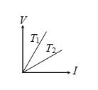
Illustration
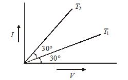
What is ratio of resistance of a given conductor at temperature {{T}_{1}} and {{T}_{2}} with help of following graph?
Solution:
{{R}_{1}}=\frac{1}{{\tan 30{}^\circ }} and {{R}_{2}}=\frac{1}{{\tan 60{}^\circ }}
Therefore \frac{{{{R}_{1}}}}{{{{R}_{2}}}}=\frac{{\tan 60{}^\circ }}{{\tan 30{}^\circ }}=\frac{3}{1}
Illustration
What is the electrical conductivity of a material of length 3m, area of cross-section \mathbf{0}\mathbf{.01}\,\mathbf{m}{{\mathbf{m}}^{\mathbf{2}}} having a resistance of 4\Omega ?
Solution:
As R=\frac{{\rho l}}{A} , and electrical conductivity
\sigma =\frac{l}{\rho } , we have
\sigma =\frac{l}{{RA}}=\frac{3}{{4\times 0.01\times {{{10}}^{{-6}}}}}=7.5\times {{10}^{7}}\,\,oh{{m}^{{-1}}}\,\,{{m}^{{-1}}}
Illustration
A given wire is stretched to reduce its diameter to half its original value. What will be its new resistance?
Solution:
Let {{l}_{1}}= Original length
{{d}_{1}}= Original diameter
{{l}_{2}}= New length
{{d}_{2}}= New diameter
Step- 1: After stretching the wire, volume (or density) of the wire remains the same
i.e., {{A}_{1}}{{l}_{1}}={{A}_{2}}{{l}_{2}}
or, \frac{{\pi d_{1}^{2}}}{4}{{l}_{1}}=\frac{{\pi d_{2}^{2}}}{4}{{l}_{2}}
or, {{l}_{2}}={{\left( {\frac{{{{d}_{1}}}}{{{{d}_{2}}}}} \right)}^{2}}{{l}_{1}}
Since, {{d}_{2}}=\frac{{{{d}_{1}}}}{2}
New length, {{l}_{2}}=4{{l}_{1}}
Step- 2: We know
R=\rho \frac{l}{A}=\rho \frac{{4l}}{{\pi {{d}^{2}}}}
{{R}_{1}}=\frac{{4{{l}_{1}}\rho }}{{\pi d_{1}^{2}}}
and {{R}_{2}}=\frac{{4{{l}_{2}}\rho }}{{\pi d_{2}^{2}}}
\frac{{{{R}_{2}}}}{{{{R}_{1}}}}=\frac{{{{l}_{2}}d_{1}^{2}}}{{{{l}_{1}}d_{2}^{2}}}=\frac{{4{{l}_{1}}d_{2}^{2}\times 4}}{{{{l}_{1}}\times d_{1}^{2}}}=16
New resistance, {{R}_{2}}=16\,\,{{R}_{1}}
Hence, the new resistance of the wire will be 16 times of the original resistance.
Illustration
A copper coil has a resistance of 20.0\,\Omega at 0°C and a resistance of 26.4\Omega at 80°C. Find out the temperature coefficient of resistance of copper.
Solution:
{{R}_{{80{}^\circ C}}}={{R}_{{0{}^\circ C}}}[1+\alpha \,\Delta T]
26.4\Omega =20.0\Omega \,\,[1+\alpha (80-0)]
\frac{{26.4-20}}{{20\times 80}}=\alpha
or \alpha =\frac{{6.4}}{{20\times 80}}=4\times {{10}^{{-3}}}{{({}^\circ C)}^{{-1}}}
Illustration
The resistance of a platinum wire of platinum resistance thermometer at the ice point is
5 W and at steam point is 5.39 W. When the thermometer is inserted in a hot bath, the resistance of the platinum wire is 5.795W. Calculate the temperature of the bath.
Solution:
Rt = R0 (1 + at)
or Rt-R0 = R0αt . . . (i)
Also, R100 = R0 (1 + 100 a)
or, R100 – R0 = 100 R0a. . . .(ii)
Dividing equation (i) by equation (ii)
\frac{{{{R}_{0}}\alpha t}}{{100{{R}_{0}}\alpha }}=\frac{{{{R}_{t}}-{{R}_{0}}}}{{{{R}_{{100}}}-{{R}_{0}}}} x 100
or, t = \frac{{5.795-5}}{{5.23-5}}\times 100 = 345.65°C.
Illustration
A wire has a resistance R. What will be its resistance,
(a)
if it is doubled on itself,
(b)
if it is stretched so that
(i) its length is doubled
(ii) its radius is halved ?
Solution
For a wire,
R = r \displaystyle \frac{L}{S}=\rho \frac{L}{{\pi {{r}^{2}}}}
If its dimensions are changed without changing its mass, its volume remains constant,
V = V’ or SL = S‘L’
(a)
When the wire is doubled on itself, its length is halved and its area of cross-section is doubled.
S x L = S´ x (L/2) or S’ = 2S
R’ = \displaystyle \rho \frac{{L’}}{{S’}}=\rho \frac{{\left( {L/2} \right)}}{{\left( {2S} \right)}}=\frac{1}{4}\rho \frac{L}{S}=\frac{1}{4}R
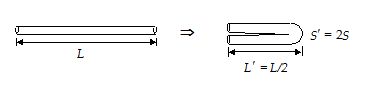
(b)
(i) When the length of the wire is doubled by stretching it,
S x L = 2L x S’ or S’ = S/2
R’ = r \displaystyle \frac{{L’}}{{S’}}=\rho \frac{{2L}}{{S/2}}=\rho \frac{{4L}}{S}=4\rho \frac{L}{S}=4R
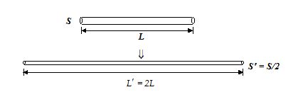
(ii)
When the wire is stretched so as to reduce its radius to half (r¢ = r/2), we have
S’ = πr’2 = π(r/2)2 = πr2/4 = S/4
From S x L = S’ x L’ = (S/4) x L’
L’ = 4L
R = r \displaystyle \frac{{L’}}{{S’}}=\rho \frac{{\left( {4L} \right)}}{{\left( {S/4} \right)}}=16\rho \frac{L}{S}=16\,R
Illustration
A metallic sphere of radius a is surrounded by a concentric thin metallic sheet of radius b. The space between these two electrodes is filled with a homogeneous poorly conducting material of resistivity r.
(a)
Find the resistance between the two electrodes.
(b)
Also derive an expression for the current density as a function of radius r, if the potential difference between the electrodes is V.
Solution
(a)
Consider a thin spherical layer between radii r and r + dr. The lines of current at all points of this layer are perpendicular to it. Therefore, such a layer can be treated as a conductor of length dr and cross-sectional area 4πr2. Thus,
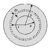
dR = r \frac{{dr}}{{4\pi {{r}^{2}}}}
R = \int\limits_{a}^{b}{{dR}}=\int\limits_{a}^{b}{{\frac{{\rho \text{ }dr}}{{4\pi {{r}^{2}}}}}}=\frac{\rho }{{4\pi }}\left[ {\frac{{-\text{1}}}{r}} \right]_{a}^{b}=\frac{\rho }{{4\pi }}\left( {\frac{1}{a}-\frac{1}{b}} \right)
(b)
The current density is given by
J=\frac{I}{S}=\frac{V}{{RS}}
At a radius r, S = 4πr2.
J\text{ }(r)=\frac{V}{{4\pi {{r}^{2}}}}\frac{{4\pi }}{\rho }\left( {\frac{{a\text{ }b}}{{b-a}}} \right)=\frac{V}{{\rho {{r}^{2}}}}\left( {\frac{{a\text{ }b}}{{b-a}}} \right)
Illustration
(a)
At what temperature would the resistance of a copper conductor be double of its value at 0°C.
(b)
Does this same temperature hold for all copper conductors, regardless of shape and size?
(aCu = 4.0 x 10⁻³/C°)
Solution
(a)
The resistance of a wire varies with temperature according to the relation
R = R0(1 + αΔθ)
So \displaystyle \frac{{{{R}_{2}}}}{{{{R}_{1}}}}=\frac{{{{R}_{0}}\left[ {1+\alpha \left( {{{T}_{2}}-0} \right)} \right]}}{{{{R}_{0}}\left[ {1+\alpha \left( {{{T}_{1}}-0} \right)} \right]}}=\frac{{\left( {1+\alpha {{T}_{2}}} \right)}}{{\left( {1+\alpha {{T}_{1}}} \right)}}
Here, R2 = 2R1 and t1 = 0
so 2 = 1 + aT2 or t2 = 1/a = 1/(4 x 10-3) = 250°C
(b)
As here T2 = (1/a), does not include dimensions of the conductor (L and S), it is valid for all copper conductors whatever be their shape and size.
Practice Questions (Basic Level)
BASIC LEVEL QUESTIONS ON CONCEPT OF DRIFT VELOCITY, OHM’S LAW
Q.1
A steady current flows in a metallic conductor of non—uniform cross section. The quantity/quantities constant along the length of the conductor is/are
(a) current, electric field and drift speed
(b) drift speed only
(c) current and drift speed
(d) current only
Ans. (d)
Q.2
Electrons in a conductor have no motion in the absence of a potential difference across it.
(a) Always True
(b) always false
(c) may be true
(d) none
Ans. (b)
Q.3
Which of the following statement is correct?
(a) Electrons drifting in a conductor under the influence of an electric field are accelerated by the field.
(b) The drift speed of the electrons in a conductor is of the order of a few mms–1.
(c) All free electrons in a metal drift from a lower to a higher potential.
(d) Since the drift speed of electrons in metal is very small and the charge on an electron is extremely small, only a small amount of current can flow in metals.
Ans. (b)
Q.4
A uniform copper wire of length 1m and cross sectional area 5 × 10⁻⁷ m2 carries a current of 1A. Assuming that there are 8 × 1028 free electrons per m3 in copper, how long will an electron take to drift from one end of the wire to the other?
(a) 0.8 × 10³ s
(b) 1.6 × 10³ s
(c) 3.2 × 10³ s
(d) 6.4 × 10³ s
Ans. (d)
Q.5
In a discharge tube, the number of protons drifting across any cross-section is 1.0 × 10¹⁸ per second while the number of electrons drifting in the opposite direction across another cross-section is 2.0 × 10¹⁸ per second. If the voltage across the tube is 240V, what is the effective resistance of the tube?
(a) 300 W
(b) 400 W
(c) 500 W
(d) 600 W
Ans. (c)
Q.6
If no potential difference is maintained between the ends of a conductor
(a) the free electrons move randomly in all directions
(b) the rate at which electrons pass through a certain cross-section from right to left is equal to the rate at which electrons pass through it from left to right
(c) no current flows through the conductor
(d) All of the above
Ans. (d)
Q.7
Choose the wrong statements from the following.
(a) In copper the number of free electrons is of the order of 1029 electrons per cubic meter
(b) At room temperature, the free electrons move with very small velocities in the absence of an electric field.
(c) In metals, the drift speed is of the order of a few mms–1
(d) In insulators, the number of free electrons is negligibly small.
Ans. (b)
Q.8
The drift speed of the free electrons in a conductor depends upon
(a) the material of the conductor
(b) the temperature of the conductor
(c) the potential difference applied across the ends of the conductor
(d) the area of cross-section of the conductor.
Ans. (b)
Q.9
A constant potential difference is maintained between the ends of a conductor having non-uniform cross-section. which of the following quantities will not change along the length of the conductor?
(a) drift speed
(b) electric field
(c) resistance
(d) current
Ans. (d)
Q.10
A current of 1A flows through a copper wire. The number of electrons passing through any cross-section of the wire in 1.6s is (charge of a electron = 1.6 × 10⁻¹⁹C)
(a) 1019
(b) 1022
(c) 1025
(d) 1028
Ans. (a)
Q.11
A uniform wire of length 2.0 m and cross-sectional area 10–7m2 carries a current of 1.6A. If there are 1028 free electrons per m3 in copper, the drift speed of electrons in copper is
(a) 2 mms—1
(b) 5 mms–1
(c) 10 mms–1
(d) 1 ms–1
Ans. (c)
Q.12
A uniform wire of length 2.0 m and cross-sectional area 10–7m2 carries a current of 1.6A. If there are 1028 free electrons per m3 in copper, the time taken by the electrons to drift from one end of the wire to the other is
(a) 200 s
(b) 100 s
(c) 20 s
(d) 2 s
Ans. (a)
Q.13
A current I is passing through a wire having two sections P and Q of uniform diameters d and d/2 respectively. If the mean drift velocity of electrons in section P and Q is denoted by vP and vQ respectively, then
(a) {{v}_{P}}={{v}_{Q}}
(b) {{v}_{P}}=\frac{1}{2}{{v}_{Q}}
(c) {{v}_{P}}=\frac{1}{4}{{v}_{Q}}
(d) {{v}_{P}}=2{{v}_{Q}}
Ans : (c)
Q.14
The current–voltage (I–V) graphs for a given metallic wire at two different temperatures T1 and T2 are shown in the figure. It follows from the graphs that
(a) T1 > T2
(b) T1 < T2
(c) T1 = T2
(d) T1 is greater or less than T2 depending on whether the resistance R of the wire is greater or less than the ratio V/I.
Ans . (a)
Q.15
Two sources of emf 6V and internal resistance 3W and 2W are connected to an external resistance R as shown. If potential difference across source A is zero, then value of R is
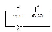
(a) 1 W
(b) 2W
(c) 3 W
(d) 4W
Ans : a
Practice Questions (JEE Main Level)
Lorem ipsum dolor sit amet, consectetur adipiscing elit. Ut elit tellus, luctus nec ullamcorper mattis, pulvinar dapibus leo.
Practice Questions (JEE Advance Level)
Q.1
In order to increase the resistance of a given wire of uniform cross section to four times its value, a fraction of its length is stretched uniformly till the full length of the wire becomes 1.5 times the original length the value of this fraction will be
(a) 1/4
(b) 1/8
(c) 1/16
(d) 1/6
Ans : (b)
Q.2
An insulating pipe of cross-section area A contains an electrolyte which has two types of ions® their charges being –e and +2e. A potential difference applied between the ends of the pipe result in the drifting of the two types of ions, having drift speed = v (–ve ion) and v/4 (+ve ion). Both ions have the same number per unit volume = n. The current flowing through the pipe is
(a) nev A/2 (b) nev A/4 (c) 5nev A/2 (d) 3nev A/2
Ans : (b)
Q.3
Current density in a cylindrical wire of radius R is given as J = \left\{ \begin{array}{l}{{J}_{0}}\left( {\frac{x}{R}-1} \right)\,\text{for}\,0\le x<\frac{R}{2}\,\,\,\\{{J}_{0}}\left( {\frac{x}{R}} \right)\,\text{for}\,\,\frac{R}{2}\le x\le R\,\,\,\end{array} \right.. The current flowing in the wire is
(a) \frac{7}{{24}}rJoR2
(b) \frac{1}{6}rJoR2
(c) \frac{7}{{12}}rJoR2
(d) \frac{5}{{12}}rJoR2
Ans : (d)