Video Lecture
Theory For Making Notes
BIOT- SAVART LAW
The Biot-Savart law is a mathematical description of the magnetic field d \vec{B} that arises from a current I flowing along an infinitesimal path element d \vec{l}
It is the product of current and length of infinitesimal segment of current carrying wire.
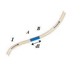
Current element AB =Id \vec{l}
The current element is taken as a vector quantity. Its direction is same as the direction of current.
Consider a point P near a conductor carrying current I . Let there is a small length d \vec{l} of conductor whose magnetic field is d \vec{B} at point P.
The nature and magnitude of magnetic field is given by the following four points
1.
The magnetic field grows weaker as we move farther from its source. In particular, the magnitude of the magnetic field d \vec{B} is inversely proportional to the square of the distance from the current element Id \vec{l}.
2.
The larger the electric current, the larger is the magnetic field. In particular, the magnitude of the magnetic field d \vec{B} is proportional to the current I.
3.
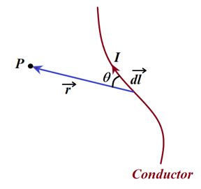
The magnitude of the magnetic field d \vec{B} is proportional to sin q, where q is the angle between the direction of current element Id \vec{l} and vector \hat{r} that points from the current element to the point in space where dB is evaluated.
4.
The direction of the \vec{B} -is not radially away from its source as the gravitational field and the electric field are from their sources. In fact, the direction of d \vec{B} is perpendicularto both Idl and the vector \hat{r} .
These four points of the magnetic field can be combined and written mathematically as
d \vec{B} = \frac{{{{\mu }_{0}}}}{{4\pi }}\ \frac{{Id\vec{l}\ \times \ \vec{r}}}{{{{r}^{3}}}}
or d \vec{B} = \frac{{{{\mu }_{0}}}}{{4\pi }}\ \frac{{Id\vec{l}\ \times \ \hat{r}}}{{{{r}^{2}}}} …(i)
where \hat{r} is a unit vector that points from the current element to the point in space where d \vec{B} is to be evaluated. The constant mo is called the permeability of free space or the permeability constant. Its value is defined to be
μo = 4π x 10–7 T m/A
The direction of the magnetic field element dB as given by Biot Savart law is shown in the figure.
The direction of \vec{B} can be obtained from the cross product d\vec{l}\ \times \ \vec{r} given in equation (i) using right hand thumb rule.
Some important features of Biot-Savart’s law:
1.
BiotSavart’s law is applicable only to a very small length of conductor carrying current.
2.
The direction of d \vec{B} is perpendicular to both d \vec{l} and \vec{r} .
3.
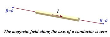
If θ = 0°, i.e. point P lies on the axis of the linear conductor carrying current, then
4.
If θ = 90°, i.e. the point P lies at a perpendicular position w.r.t. to current, then
dB = \frac{{{{\mu }_{0}}}}{{4\pi }}\frac{{Id\ell }}{{{{r}^{2}}}} , which is maximum.
Right hand thumb rule :
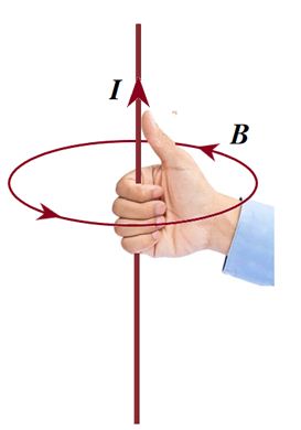
According to this rule if a straight current carrying conductor is held in the right hand such that the thumb of the hand represents the direction of current flow, then the direction of folding fingers will represent the direction of magnetic lines of force.
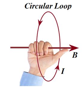
Right hand thumb rule of circular currents : According to this rule if the direction of current in circular conducting coil is in the direction of folding fingers of right hand, then the direction of magnetic field will be in the direction of stretched thumb
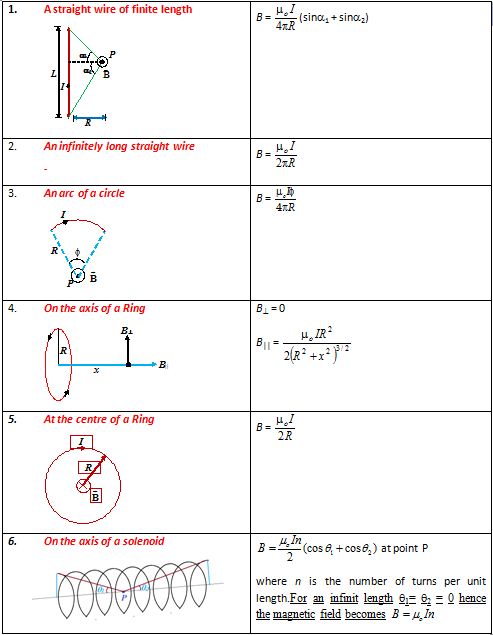
Applications Of Biot-Savart Law
Magnetic field due to different current systems
Please Note that here we are giving only the final formula of magnetic field in different cases. For detailed derivation kindly refer to the video lectures
Illustration
In a hydrogen atom, the electron is making 6.6 x 10¹⁵ revolutions per second in a circular orbit of radius 0.53 Å. The field of induction produced at the position of the nucleus is approximately
(1) zero
(2) 3πT
(3) 4πT
(4) 0.4πT
Solution:
i= Ne = (6.6\times {{10}^{5}}\times 1.6\times {{10}^{{-19}}})\ amp
B = \frac{{{{\mu }_{0}}}}{{4\pi }}\cdot \frac{{2\pi ni}}{r}
= {{10}^{{-7}}}\times 2\pi \times (1)\frac{{(6.6\times {{{10}}^{5}}\times 1.6\times {{{10}}^{{-19}}})}}{{0.53\times {{{10}}^{{-10}}}}} = 4π tesla
∴ (3)
Illustration
A copper wire having resistance 0.01 ohm in each metre is used to wind a 400 turn solenoid of radius 1 cm and length 20 cm. Find the e.m.f of the battery which when connected across the solenoid will produce a magnetic field 1 x 10⁻² tesla at the centre of solenoid.
(1) 1 volt
(2) 2 volts
(3) 2.5 volts
(4) 3 volts
Solution:
One turn has a length = 2πr = 2π x 1 x 10–2m
No. of turns = 400
Total length = 400 x 2π x 10–2 m
Resistance (R) = 400 x 2π x 10–2x 0.01 ohm = 800 π x 10–4 ohm
Magnetic field = μ0ni
1 x 10–2 = {{\mu }_{0}}\times \frac{{400}}{{20\ \times \ {{{10}}^{{-2}}}}}\ \times \ i
But i = \frac{E}{R}\ =\ \frac{E}{{8{{\pi }^{2}}\times \ {{{10}}^{{-4}}}}}
\frac{{20\ \times \ {{{10}}^{{-2}}}\times \ 1\ \times \ {{{10}}^{{-2}}}}}{{400\ {{\mu }_{0}}}}\ =\ \frac{E}{{{{{10}}^{{-4}}}\times \ 800\ \pi }}
E = \frac{{800\ \pi \ \times \ {{{10}}^{{-4}}}\times \ 20\ \times \ {{{10}}^{{-4}}}}}{{400\ \times \ 4\pi \ \times \ {{{10}}^{{-7}}}}} = 1 volt
∴ (1)
Illustration
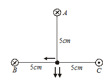
Three very ling wires perpendicular to the plane of the paper, the carrying 5A each in the direction shown in the figure. What is the B-field at the point midway between B and C shown by a dot?
Solution:
The magnetic field due to B
=\frac{{{{\mu }_{o}}I}}{{2\pi d}}=\frac{{4\pi \times {{{10}}^{{-7}}}}}{{2\pi }}\frac{I}{d}
=\frac{{2I}}{d}\times {{10}^{{-7}}}
=\frac{{2\times 5}}{{0.05}}\times {{10}^{{-7}}}
=2\times {{10}^{{-5}}} T perpendicular to BC (downward)
The magnetic field due to the conductor at C is of the same magnitude and direction. The field due to the conductor at A is of the same magnitude, but its direction is along CB.
The result field =\sqrt{{{{4}^{2}}+{{2}^{2}}}}\times {{10}^{{-5}}}=\sqrt{{20}}\times {{10}^{{-5}}}
=4.48\times {{10}^{{-5}}} Tesla.
Illustration
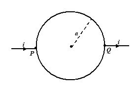
A cell is connected across two points P and Q of a uniform circular conductor. Prove that the magnetic field at its center O will be zero.
Solution:
Let {{l}_{1}},\,\,{{l}_{2}} be the lengths of the two parts PRQ and PSQ of the conductor and \rho be the resistance per unit length of the conductor.
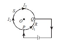
The resistance of the portion PRQ will be, {{R}_{1}}={{l}_{1}}\rho
The resistance of the portion PRQ will be {{R}_{2}}={{l}_{2}}\rho . Let {{I}_{1}},\,\,{{I}_{2}} be the current in PRQ and PSQ respectively. Since these parts are in parallel, the potential differnce across their ends will be same
{{I}_{1}}{{R}_{1}}={{I}_{2}}{{R}_{2}}
Or {{I}_{1}}{{l}_{1}}\rho ={{I}_{2}}{{l}_{2}}\rho
or {{I}_{1}}{{l}_{1}}={{I}_{2}}{{l}_{2}} …(i)
According to Biot-Savart’s law, the magnetic fields at the center O due to current through circular conductors PRQ and PSQ will be
{{B}_{1}}=\frac{{{{\mu }_{1}}}}{{4\pi }}\frac{{{{I}_{1}}{{l}_{1}}\,\sin 90{}^\circ }}{{{{r}^{2}}}}
and {{B}_{2}}=\frac{{{{\mu }_{0}}}}{{4\pi }}\frac{{{{I}_{2}}{{l}_{2}}\,\sin 90{}^\circ }}{{{{r}^{2}}}}
Since, {{I}_{1}}{{l}_{1}}={{I}_{2}}{{l}_{2}}
{{B}_{1}}={{B}_{2}}
According to right hand rule, the directions of {{B}_{1}} and {{B}_{2}} are opposite to each other, Hence, the resultant magnetic field at O will be zero.
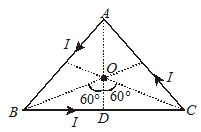
Illustration
A current of 1A is flowing in the sides of an equilateral triangle of side 4.5\times {{10}^{{-2}}} m. Find the magnetic field at the centroid of the triangle.
Solution:
Let I be the current flowing in the sides of the triangle. The magnetic field induction at the centroid O due to current through one side BC of the triangle will be
{{B}_{1}}=\frac{{{{\mu }_{o}}}}{{4\pi }}\frac{I}{R}(\sin {{\varphi }_{1}}+\sin {{\varphi }_{2}})
Total magnetic field induction at O due to current through all the three sides of a triangle will be
B=3{{B}_{1}}=\frac{{3{{\mu }_{o}}}}{{4\pi }}\frac{I}{R}\,(\sin {{\varphi }_{1}}+\sin {{\varphi }_{2}})
Here, I=1A;\,\,\,{{\varphi }_{1}}=60{}^\circ ={{\varphi }_{2}}
and R=OD=BD/\tan 60{}^\circ =\frac{{a/2}}{{\sqrt{3}}}=\frac{a}{{2\sqrt{3}}}=\frac{{4.5\times {{{10}}^{{-2}}}}}{{2\sqrt{3}}}m
B=3\times {{10}^{{-7}}}\times \frac{{2\sqrt{3}}}{{4.5\times {{{10}}^{{-2}}}}}(\sin 60{}^\circ +\sin 60{}^\circ )
=\frac{{3\times 2\sqrt{3}}}{{4.5}}\times {{10}^{{-5}}}\left( {\frac{{\sqrt{3}}}{2}+\frac{{\sqrt{3}}}{2}} \right)
=4\times {{10}^{{-5}}}T
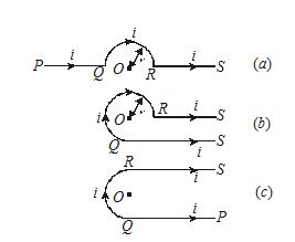
Illustration
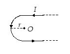
Find the magnetic field induction at a point O if the current carrying wire has the shape shown in figure (a), (b), (c). The radius of the curved part of the wire is , the linear parts are assumed to be very long.
Solution:
(a)
Magnetic field induction at O due to current through straight wires PQ and RS is zero. The magnetic field induction at O due to current through semicircular part QR of wire is given by
{{B}_{1}}=\frac{{{{\mu }_{o}}}}{{4\pi }}\times \frac{{\pi i}}{r} (It acts \bot r to the plane of the current loop downwards).
B=0+\frac{{{{\mu }_{o}}}}{4}\times \frac{i}{r}=\frac{{{{\mu }_{o}}}}{4}\times \frac{i}{r}
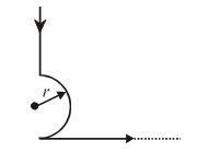
(b)
Magnetic field induction at O due to current through straight portion PQ.
{{B}_{1}}=\frac{{{{\mu }_{o}}}}{{4\pi }}\times \frac{i}{r}\,(\sin 0{}^\circ +\sin 90{}^\circ )=\frac{{{{\mu }_{o}}}}{{4\pi }}\frac{i}{r} acting \bot r to loop downwards.
Magnetic field induction at O due to current through curved part QR of the wire is
{{B}_{2}}=\frac{{{{\mu }_{o}}}}{{4\pi }}\times \frac{{3\pi }}{2}\times \frac{i}{r}=\frac{{{{\mu }_{o}}}}{{4\pi }}\frac{i}{r}\times \frac{{3\pi ;}}{2} acting \bot r to loop downwards
Magnetic field induction at O due to current through straight wire RS is zero.
B={{B}_{1}}+{{B}_{2}}=\frac{{{{\mu }_{o}}}}{{4\pi }}\frac{i}{r}+\frac{{{{\mu }_{o}}}}{{4\pi }}\frac{i}{r}\times \frac{{3\pi }}{2}=\frac{{{{\mu }_{o}}}}{{4\pi }}\frac{i}{r}\left( {1+\frac{{3\pi }}{2}} \right)
(c)
In this case, the effective magnetic field induction at O due to current through the entire wire will be
B=\frac{{{{\mu }_{o}}}}{{4\pi }}\frac{i}{r}+\frac{{{{\mu }_{o}}}}{{4\pi }}\frac{{\pi i}}{r}+\frac{{{{\mu }_{o}}}}{{4\pi }}\frac{i}{r}=\frac{{{{\mu }_{o}}}}{{4\pi }}\frac{i}{r}(2+\pi )
Illustration
A solenoid of length l and radius a has N turns of wire and carries a current I. Find the field strength at a point along the axis.
Solution
Since the solenoid is a series of closely packed loops. We may use equation (iii) for the field on the axis of a current carrying loop. The solenoid is divided into current loops of width dy, as in figure (a), each of which contains ndy turns, where n = N/l is the number of turns per unit length. The current within such a loop is (n dy)I. From the diagram we see that
y = a tan θ
from which dy = a sec2θ dθ
Thus, I in equation (iii) is replaced by
nIdy = nIa sec2θ dθ
After substituting for I and y in equation (iii) and simplifying, we find
dB = \frac{{{{\mu }_{o}}nI{{a}^{3}}\ {{{\sec }}^{2}}\ \theta \,d\theta }}{{2{{{({{a}^{2}}+{{a}^{2}}{{{\tan }}^{2}}\theta )}}^{{3/2}}}}}=\frac{1}{2} μonI cos θ dθ
For a finite solenoid, the total field strength is
B = \frac{1}{2} μonI \int\limits_{{{{\theta }_{1}}}}^{{{{\theta }_{2}}}}{{}} cos q dθ = \frac{1}{2} μonI (sin θ2 – sin θ1)
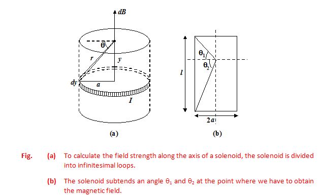
If the solenoid is infinite long, θ1 = -90° and θ2 = +90°, therefore, the field at the axis of the solenoid is
B = μonI
Illustration
(a)
What is the magnetic field produced by a point charge q moving at velocity v ?
(b)
What is the force between two equal charges moving parallel to each other with the same velocity ?
Solution
(a)
The Biot-Savart law refers the magnetic field produced by a current element, Id \vec{l}
Since I = dq/dt we rewrite
Id \vec{l} = \frac{{dq}}{{dt}} d \vec{l}
= dq \frac{{d\vec{l}}}{{dt}} = (dq) \vec{v}
where \vec{v} is the velocity of the charge q. From equation (i), we infer that the field due to a single charge q moving at velocity v is
\vec{B}= \frac{{{{\mu }_{o}}}}{{4\pi }}\ \frac{{q\vec{v}\ \times \ \vec{r}}}{{{{r}^{3}}}}
The magnetic field lines are circular, as shown in figure, (a).
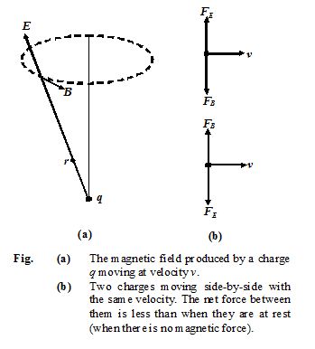
(b)
In Fig.(b), the repulsive force between the charges is
FE= \frac{{k{{q}^{2}}}}{{{{d}^{2}}}}=\frac{1}{{4\pi {{\varepsilon }_{0}}}}\ \ \frac{{{{q}^{2}}}}{{{{d}^{2}}}}
The magnitude of the magnetic force
{{\vec{F}}_{B}} = q \vec{v} ´ \vec{B} exerted by one charge on the other is
FB = (qv) \left( {\frac{{{{\mu }_{o}}}}{{4\pi }}\ \frac{{qv}}{{{{d}^{2}}}}} \right)\ =\ \frac{{{{\mu }_{o}}}}{{4\pi }}\ \frac{{{{q}^{2}}{{v}^{2}}}}{{{{d}^{2}}}}
This force is attractive.
The net forced between the charge is
F = FE– FB= \frac{{{{q}^{2}}}}{{4\pi {{d}^{2}}}}\left[ {\frac{1}{{{{\varepsilon }_{o}}}}-{{\mu }_{o}}{{v}^{2}}} \right]
Since c2= \frac{1}{{{{\mu }_{o}}{{\varepsilon }_{o}}}}, therefore,
F = \frac{{{{q}^{2}}}}{{4\pi {{\varepsilon }_{o}}{{d}^{2}}}}\left[ {1-\frac{{{{v}^{2}}}}{{{{c}^{2}}}}} \right]
The net force on each of the particles moving with the same velocity is less than that when they are at rest.
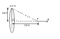
Illustration 14
A charge of 1C is placed at one end of a non-conducting rod of length 0.6m. The rod is rotated in a vertical plane about a horizontal axis passing through the other end of the rod with angular frequency 104p rad/s. Find the magnetic field at a point on the axis of rotation at a distance of 0.8 m from the centre of the path. Now, half of the charge is removed from one end and placed on the other end. The rod is rotated in a vertical plane about a horizontal axis passing through the mid point of the rod with the same angular frequency. Calculate the magnetic field at a point on the axis at a distance of 0.4m from the centre of the rod.
Solution:
A revolving charge is equivalent to a current
l = q.f = \displaystyle q.\frac{\omega }{{2\pi }} = \displaystyle 1\times \frac{{{{{10}}^{4}}\pi }}{{2\pi }}=5\times {{10}^{3}}A
The field at a distance z from the centre of the axis of a current carrying coil is given by,
\displaystyle B=\frac{{{{\mu }_{0}}{{a}^{2}}l}}{{2{{{({{a}^{2}}+{{z}^{2}})}}^{{3/2}}}}}
\displaystyle \frac{{4\times {{{10}}^{{-7}}}\times 5\times {{{10}}^{3}}{{{(0.6)}}^{2}}}}{{2{{{[{{{(0.6)}}^{2}}+{{{(0.8)}}^{2}}]}}^{{3/2}}}}}
Equivalent current
I’ \displaystyle \frac{q}{2}f+\frac{q}{2}f=qf=5\times {{10}^{3}}A
Magnetic field at P in this case
B’ = \displaystyle =\frac{{{{\mu }_{0}}I{{a}^{2}}}}{{2{{{({{a}^{2}}+{{z}^{2}})}}^{{3/2}}}}}
Here, a = 0.3 m, z = 0.4 m
Which gives,
B’ = 2.26 x 10⁻³ T
Illustration
Find the magnitude and direction of magnetic field at point P due to the current carrying wire as shown.
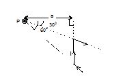
Here,θ1 = – 30°, θ2 = 60°,
putting these values , we get
\displaystyle \vec{B} = \displaystyle \frac{{{{\mu }_{0}}i}}{{4\pi a}}\left[ {-1/2+\sqrt{3}/2} \right](\hat{k})
Practice Questions (Basic Level)
Q.1
Two infinitely long wires carrying current i are bent, as shown in the figure. The magnetic induction at the centre C is equal to
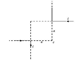
(a) zero
(b) \frac{{{{\mu }_{o}}I}}{{2\pi a}}
(c) \frac{{{{\mu }_{o}}I}}{{4\pi a}}
(d) \frac{{{{\mu }_{o}}I}}{{\pi a}}
Ans. (b)
Q.2
If the resistance of the upper half of a rigid loop is twice of that of the lower half, the magnitude of magnetic induction at the centre is equal to
(a) zero
(b \frac{{{{\mu }_{o}}I}}{{4a}}
(c) \frac{{{{\mu}_{o}}I}}{{12a}}
(d) none of these.
Q.3
The resulting magnetic field at the point ‘O’ due to the current carrying wire shown in the figure
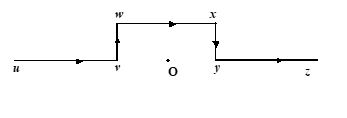
(a) points vertically upwards
(b) points vertically downwards
(c) is zero
(d) is the same as due to the segment wx alone.
Q.4.
The magnetic field at the centre of a current-carrying circular coil depends on the radius R of the coil as
(a) R (b) R2 (c) 1/R (d) 1/R2
Ans : (c)
Q.5
The value of the magnetic field at a distance x from a long straight current-carrying conductor is proportional to:
(a) x (b) x2 (c) 1/x2 (d) 1/x
Ans : (d)
Q.6
A circular coil has one turn and carries a current I. The same wire is wound into a smaller coil of 4 turns and the same current is passed through it. The field at the centre
(a) decreases to \frac{1}{4} the value
(b) is the same
(c) increases to 16 time the value
(d) decreases to 16 times the value
Ans : (c)
Q.7
A battery is connected between two points A and B on the circumference of a uniform conducting ring of radius r and resistance R. One arc AB of the ring subtends an angle q at the centre. The value of the magnetic induction at the centre due to the current in the ring is
(a) proportional to 2(180o – q)
(b) inversely proportional to r
(c) zero only if q = 180o
(d) zero for all values of q
Ans : (d)
8.
Two infinitely long, parallel wires carry equal currents of 2.5 amp in the same direction. The conductors are 5 cm apart. Calculate the field (B–field) at the point which lies
(i)
at 2.5 cm from both the wires
(a)Zero
(b)1
(c)2
(d)5
Ans (a)
(ii)
at 5 cm from both the wires
(a) {{10}^{{5}}}\,\,tesla
(b) {{10}^{{-5}}}\,\,tesla
(c) {{10}^{{-4}}}\,\,tesla
(d) {{10}^{{-2}}}\,\,tesla
Ans (b)
(iii)
10 cm apart from the first conductor towards the second conductors.
(a) 1.0\times {{10}^{{-5}}}\,\,tesla
(b) 2.5\times {{10}^{{-5}}}\,\,tesla
(c) 1.5\times {{10}^{{-5}}}\,\,tesla
(d) 3.0\times {{10}^{{-5}}}\,\,tesla
Ans (c)
9.
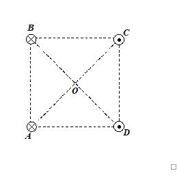
Four long copper wires, parallel to each other are perpendicular to the plane of the paper, their cross-sections forming a square 20 cm on edge. A 20 ampere current is set in each wire. The currents through the conductors at the corners B and C are perpendicular into the plane of the paper and those at the corners A and D are perpendicular out of the plane of the paper. What is the magnitude and the direction of the field at the center of the square?
(a) 8\times {{10}^{{-5}}}\,\,\mathbf{Tesla}
(b) 8\times {{10}^{{-5}}}\,\,\mathbf{Tesla}
(c) 8\times {{10}^{{-5}}}\,\,\mathbf{Tesla}
(d) 8\times {{10}^{{-5}}}\,\,\mathbf{Tesla}
Ans (C)
10.
Calculate the magnetic field at the center of a square 10 cm on each side when 1.5 ampere – current passes through it.
(a) 2.5\times {{10}^{{5}}}T
(b) 2.5\times {{10}^{{-5}}}T
(c) 1.7\times {{10}^{{5}}}T
(d) 1.7\times {{10}^{{-5}}}T
Ans (d)
Practice Questions (JEE Main Level)
Q.1
Two infinitely long, thin, insulated, straight wires lie in x–y plane along the x and y-axes respectively. Each wire carries a current I, respectively in the positive x-direction and positive y-direction. The magnetic field will be zero at all points on the straight line.
(a) y = x (b) y = –x (c) y = x – 1 (d) y = –x + 1
Ans. (a)
Q.2
The magnetic field due to a current-carrying circular coil on the axis at a large distance x from the centre of the coil varies approximately as
(a) x–1 (b) x–3/2 (c) x–3 (d) x–2
Ans. (c)
Q.3
A square coil of side a carries a current I. The magnetic field at the centre of the coil is
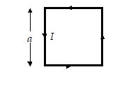
(a) \frac{{{{\mu }_{0}}I}}{{a\pi }}
(b) \frac{{\sqrt{2}{{\mu }_{0}}I}}{{a\pi }}
(c) \frac{{{{\mu }_{0}}I}}{{\sqrt{2}\text{ }a\pi }}
(d) \frac{{2\sqrt{2}{{\mu }_{0}}I}}{{a\pi }}
Ans. (d)
Q.4
In the given figure the straight parts of the wire are very long. The magnetic induction at O is
(a) \frac{{{{\mu }_{0}}I}}{{4r}}+\frac{{{{\mu }_{0}}I}}{{2\pi r}} out of the page
(b) \frac{{{{\mu }_{0}}I}}{{4r}}+\frac{{{{\mu }_{0}}I}}{{4\pi r}} out of the page
(c) \frac{{{{\mu }_{0}}I}}{{4r}}+\frac{{{{\mu }_{0}}I}}{{4\pi r}} into the page
(d) \frac{{{{\mu }_{0}}I}}{{4r}}+\frac{{{{\mu }_{0}}I}}{{2\pi r}} into the page
Ans. (b)
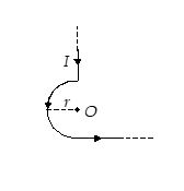
Q.5
A long thin wire is bent as shown in the figure. The radius of the semicircular part is r metres. If a current of I amperes flows through the wire, then the magnetic induction at O in tesla is
(a) \frac{{{{\mu }_{0}}I}}{{2r}}\left( {1+\frac{1}{\pi }} \right) out of the page
(b) \frac{{{{\mu }_{0}}I}}{{2r}}\left( {1+\frac{1}{\pi }} \right) into the page
(c) \frac{{{{\mu }_{0}}I}}{{4r}}\left( {1+\frac{2}{\pi }} \right) out of the page
(d) \frac{{{{\mu }_{0}}I}}{{4r}}\left( {1+\frac{2}{\pi }} \right) into the page
Ans. (c)
Q.6
Four long straight wires are located at the corners of a square ABCD. All the wires carry equal currents. Current in the wires A and B are inwards and in C and D are outwards. The magnetic field at the centre O is along
(a) AD (b) CB (c) AB (d) CD
Ans. (d)
Q.7
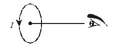
You are facing a coil through which a current i is passing in the clockwise direction. The face of the coil towards you is a
(a) North pole (b) Monopole (c) Dipole (d) South pole
Ans. (d)
Q.8
A current passes through a coil in the anti-clockwise direction. The magnetic field at a point on the axis of the coil is
(a) Perpendicular to the plane of the coil
(b) Perpendicular to the axis of the coil
(c) Along the axis towards the center of coil
(d) Along the axis away from the center of coil
Ans. (d)
Q.9
The S–pole of a magnet is placed on the axis of a circular coil carrying current in anti-clockwise direction. It experiences a force of
(a) Attraction
(b) Repulsion
(c) Neither attraction nor repulsion
(d) Both attraction and repulsion
Ans. (a)
Q.10
A circular current carrying coil has a radius R. The distance from the center of the coil, on the axis where the magnetic induction will be 1/8 th to its value at the center of the coil, is
(1) R\sqrt{3}
(2) R/\sqrt{3}
(3) \frac{{2R}}{{\sqrt{3}}}
(4) (2/\sqrt{3})R
Q.11
The magnetic induction at the center O in the following figure
(a) \frac{{{{\mu }_{0}}I}}{{4\pi r}}
(b) Zero
(c) \frac{{{{\mu }_{0}}I(\pi -1)}}{{4\pi r}}
(d) \frac{{{{\mu }_{0}}I(\pi +1)}}{{4\pi r}}
Ans. (c)
Q.12
A particle carrying a charge equal to 100 times the charge on an electron, is rotating at the rate of one rotation per second in a circular path of radius 0.08 m. The value of the magnetic field produced at the center will be ( {{\mu }_{0}}, permeability of free space)
(a) {{10}^{{-7}}}/{{\mu }_{0}}\,\,Wb/{{m}^{2}}
(b) {{10}^{{-17}}}{{\mu }_{0}}\,\,Wb/{{m}^{2}}
(c) {{10}^{{-6}}}{{\mu }_{0}}\,\,Wb/{{m}^{2}}
(d) {{10}^{{-7}}}{{\mu }_{0}}\,\,Wb/{{m}^{2}}
Ans. (b)
Q.13
A length of wire carries a steady current. It is bent to form a circular coil of one turn only. The same length is now bent more sharply to give a double loop of smaller radius. The magnetic field at the center caused by the same current is
(a) A half of its first value
(b) Unaltered
(c) A quarter of its first value
(d) Four times its first value
Ans. (d)
Q.14
Figure shows a current loop having to circular arcs joined by two radial lines
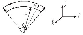
The magnetic field at O is
(a) \frac{{{{\mu }_{0}}I\theta }}{{2\pi ab}}(b-a)\hat{j}
(d) \frac{{{{\mu }_{0}}I\theta }}{{4\pi ab}}(b-a)\hat{k}
(c) Zero
(d) \frac{{{{\mu }_{0}}I\theta }}{{3\pi ab}}(b+a)\hat{k}
Ans. (b)
Q.15
A non-conducting disc of radius R has a surface density of charge \sigma and rotates about its central axis at angular speed \omega
(a) The current dI in an elementary ring of width dr is 1/2\omega \sigma rdr
(b) The magnetic field at the centre of the aforementioned elementary ring is 1/2{{\mu }_{0}}\omega \sigma rdr
(c) The magnetic field at the centre of the aforementioned elementary ring is {{\mu }_{0}}\omega \sigma rdr
(d) The total magnetic field at the centre of the disc is 1/2{{\mu }_{0}}\sigma \omega R
Ans. (d)
16.
Two infinitely long, parallel wires carry equal currents of 2.5 amp in the same direction. The conductors are 5 cm apart. Calculate the field (B–field) at the point which lies
(i)
at 2.5 cm from both the wires
(a)Zero
(b)1
(c)2
(d)5
Ans (a)
(ii)
at 5 cm from both the wires
(a) {{10}^{{5}}}\,\,tesla
(b) {{10}^{{-5}}}\,\,tesla
(c) {{10}^{{-4}}}\,\,tesla
(d) {{10}^{{-2}}}\,\,tesla
Ans (b)
(iii)
10 cm apart from the first conductor towards the second conductors.
(a) 1.0\times {{10}^{{-5}}}\,\,tesla
(b) 2.5\times {{10}^{{-5}}}\,\,tesla
(c) 1.5\times {{10}^{{-5}}}\,\,tesla
(d) 3.0\times {{10}^{{-5}}}\,\,tesla
Ans (c)
17.
Four long copper wires, parallel to each other are perpendicular to the plane of the paper, their cross-sections forming a square 20 cm on edge. A 20 ampere current is set in each wire. The currents through the conductors at the corners B and C are perpendicular into the plane of the paper and those at the corners A and D are perpendicular out of the plane of the paper. What is the magnitude and the direction of the field at the center of the square?
(a) 8\times {{10}^{{-5}}}\,\,\mathbf{Tesla}
(b) 8\times {{10}^{{-5}}}\,\,\mathbf{Tesla}
(c) 8\times {{10}^{{-5}}}\,\,\mathbf{Tesla}
(d) 8\times {{10}^{{-5}}}\,\,\mathbf{Tesla}
Ans (C)
18.
Calculate the magnetic field at the center of a square 10 cm on each side when 1.5 ampere – current passes through it.
(a) 2.5\times {{10}^{{5}}}T
(b) 2.5\times {{10}^{{-5}}}T
(c) 1.7\times {{10}^{{5}}}T
(d) 1.7\times {{10}^{{-5}}}T
Ans (d)
Practice Questions (JEE Advance Level)
Q.1
A wire carrying a current i has the configuration as shown in the figure. Two semi-infinite straight sections both tangents to the same circle are connected by a circular arc of central angle q, along the circumference of circle, with all sections lying in the same plane. If the magnetic field at center of the circle is zero, then q is equal to
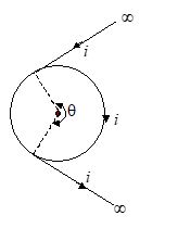
(a) \frac{\pi }{2} rad
(b) p rad
(c) 1 rad
(d) 2 rad
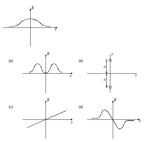
Q.2
Two straight infinitely long current carrying wires are kept along z-axis at the coordinates (0, a, 0) and (0, –a, 0) respectively as shown in the figure. The current in each of the wire is equal and along negative z-axis (into the plane of the paper). The variation of magnetic field on the x-axis will be approximately