Video Lecture
Theory For Making Notes
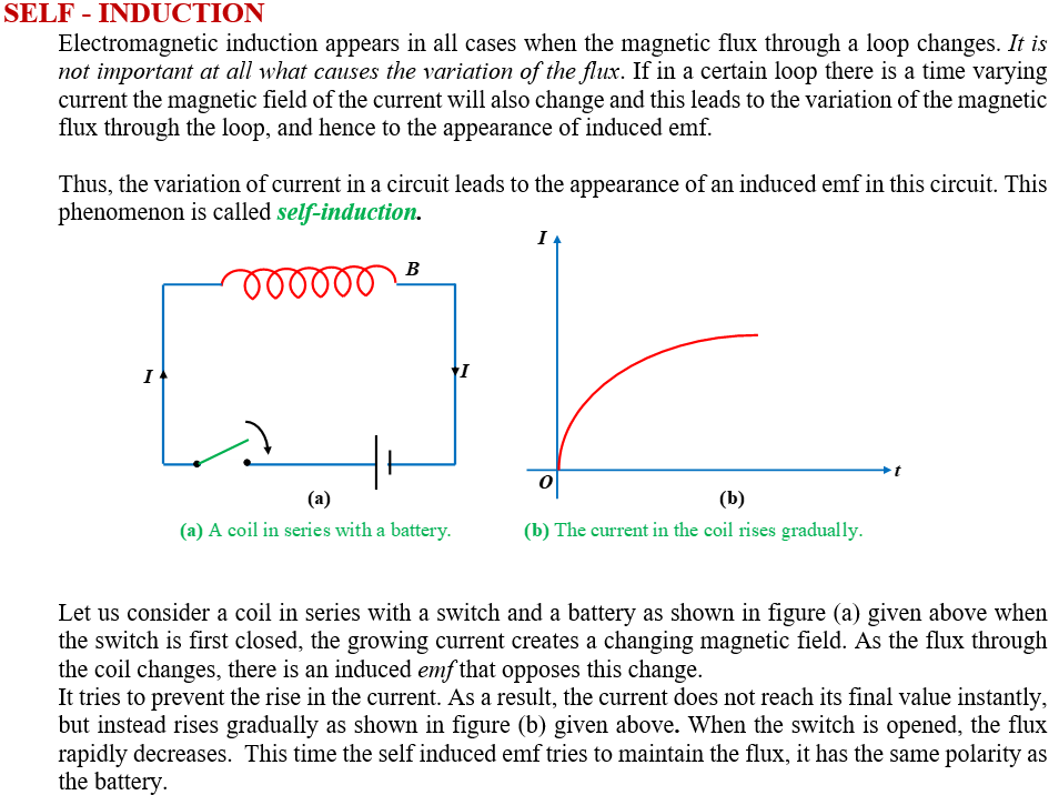
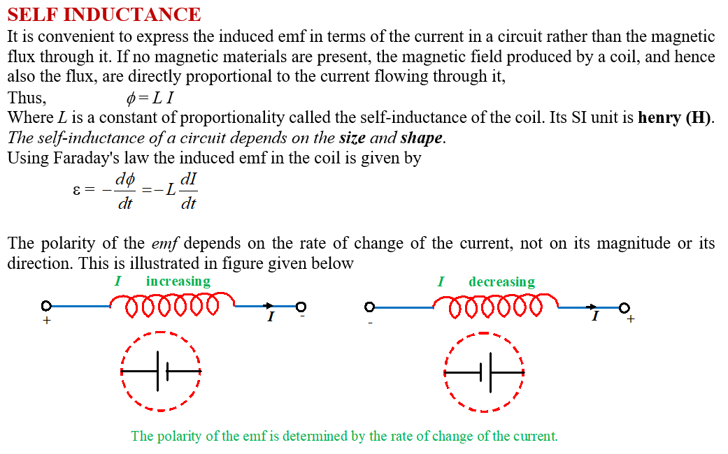
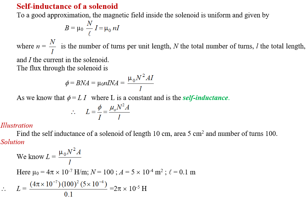
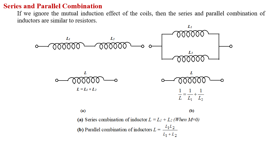
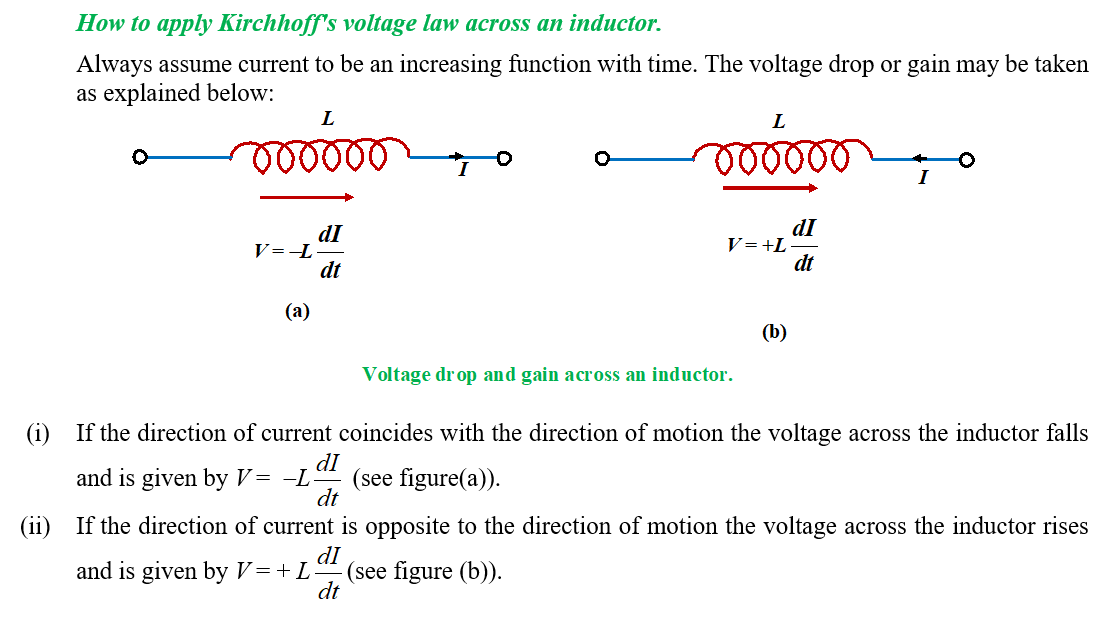
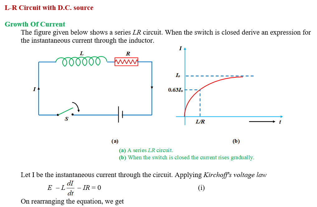
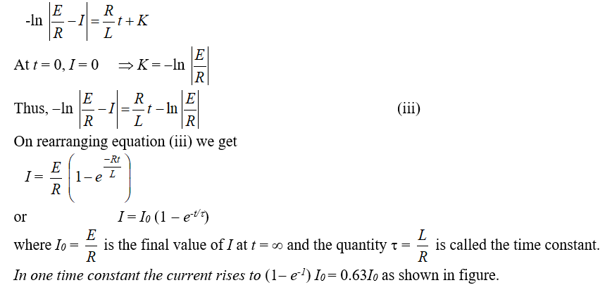
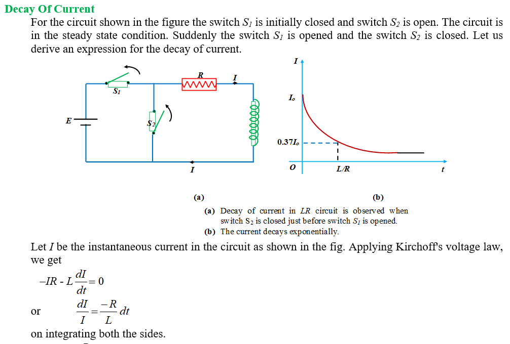

Practice Questions (Basic Level)
Q.1
Two pure inductors, each of self inductance L are connected in parallel but are well separated from each other, then the total inductance is
(a) L
(b) 2L
(c) \frac{L}{2}
(d) \frac{L}{4}
Ans : (c)
Q.2
The current through an inductor of 1 H is given by
i = 3t sin t
The voltage across the inductor of 1 H is
(a) 3 sin t + 3 cos t
(b) 3 cos t + t sin t
(c) 3 sin t – 3t cos t
(d) 3t cos t + 3 sin t
Ans : (d)
Q.3
Dimensions of self-inductance are
(a) [MLT–2 A–2]
(b) [ML2T–1 A–2]
(c) [ML2T–2 A–2]
(d) [ML2T–2 A–1]
Ans : (c)
Q.4
The minimum value of inductance which can be obtained using three inductances of values 2H, 3H and 6H is
(a) 1H (b) 1/6H (c) 1/3H (d) 1H
Ans : (a)
Q.5
The inductance of a coil in which a current of 0.1 A increasing at the rate of 0.5 A/s represents a power flow of 0.5 W is
(a) 2 H (b) 8 H (c) 20 H (d) 10 H
Ans : (d)
Practice Questions (JEE Main Level)
Q1
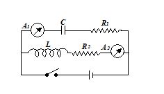
In the circuit shown in figure, A1 and A2 are ammeters, C is capacitance, L is the inductance, R1 and R2 are resistances and E is the emf. Just after key K is pressed, the reading is
(a) Maximum in both A1 and A2
(b) Zero in both A1 and A2
(c) Zero in A1 and maximum in A2
(d) Maximum in A1 and zero in A2
Ans. (d)
Q.2
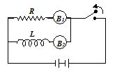
In given figure two bulbs B1 and B2 and resistance R and an inductance L are connected in given circuit.
(a) Both B1 and B2 die out promptly
(b) Both B1 and B2 die out with same delay
(c) B2 dies out promptly but B1 with some delay
(d) B1 dies out promptly but B2 with some delay
Ans. (b)
Q.3
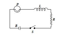
In the figure, a lamp P is in series with an iron-core inductor L. When the switch S is closed, the lamp brightness rises relatively slowly to its full brightness. This is due to
(a) the low resistance of P
(b) the low resistance of L
(c) the back emf in L
(d) the high voltage of the battery
Ans. (c)
Q.4
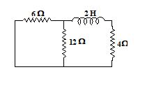
The time constant for the given circuit is
(a) 4 s
(b) \frac{1}{4}s
(c) 2 s
(d) \frac{1}{2}\,s
Ans. (b)
Q.5
The current i in an induction coil varies with time t according to the graph shown in the figure. Which of the following graphs shows the induced emf (E) in the coil with time
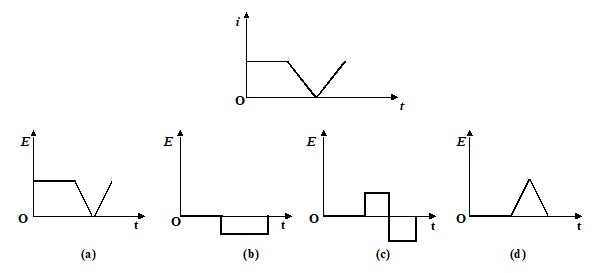
Ans. (c)
Q.6
When the number of turns in a coil is doubled without any change in the length of the coil, its self-inductance becomes
(a) four times
(b) doubled
(c) halved
(d) squared
Ans. (b)
Q.7
A uniformly wound long solenoid of inductance L and resistance R is broken into two equal parts, which are then joined in parallel. This combination is then joined to a cell of emf e. The time constant of the circuit is
(a) L/R (b) L/2R (c) 2 L/R (d) L/4R
Ans. (a)
Q.8
When a coil carrying a steady current is short-circuited, the current in it decrease h times in time t0. The time constant of the circuit is
(a) {{t}_{0}}1\text{n}\,\eta
(b) \frac{{{{t}_{0}}}}{{\ln \ \eta }}
(c) \frac{{{{t}_{0}}}}{\eta }
(d) \frac{{{{t}_{0}}}}{{\eta -1}}
Ans. (b)
Practice Questions (JEE Advance Level)
Q.1
In the circuit given in diagram the time dependence of the current flowing through the inductance L after the switch S is shorted at the moment t = 0 is
(a) I=\frac{E}{R}(1-{{e}^{{-tR/2L}}})
(b) I=\frac{E}{R}(1-{{e}^{{-tR/L}}})
(c) I=\frac{{2E}}{{3R}}(1-{{e}^{{-tR/2L}}})
(d) I=\frac{E}{R}(1-{{e}^{{-2tR/L}}})
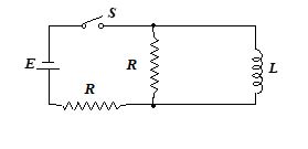
Ans : (a)
Q.2
The current in a coil of self-inductance 2.0 henry is increasing according to I = 2 sin t2A. Find the amount of energy spent during the period when the current changes from 0 to 2A.
(a) 2J (b)8J (c) 4J (d)none
Ans : (c)
Q.3
A capacitor of capacity 2 mF is charged to a potential difference of 12 V. It is then connected across an inductor of inductance 0.6 mH. Then the current in the circuit at a time when the potential difference across the capacitor is 6.0 V must be
(a) 0.6A (b)0.4A (c)4A (d) 1.5A
Ans : (a)
Comprehension ( Q.4 to Q.6)
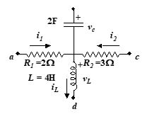
In the figure shown i1 =10e–2tA, i2 = 4A and vc = 3e–2t V.
Then
Q.4
iL and vL should be
(a) \displaystyle {{i}_{L}}=3-2{{e}^{{-3t}}},{{v}_{L}}=6{{e}^{{-2t}}}
(b) \displaystyle {{i}_{L}}=4-2{{e}^{{-t}}},{{v}_{L}}=16{{e}^{{-t}}}
(c) \displaystyle {{i}_{L}}=4-2{{e}^{{-2t}}},{{v}_{L}}=16{{e}^{{-2t}}}
(d) \displaystyle {{i}_{L}}=-2{{e}^{{-2t}}},{{v}_{L}}=1-16{{e}^{{-2t}}}
Ans : (c)
Q.5
vac, vab and vcd should be
(a) \displaystyle {{v}_{{ac}}}=20{{e}^{{-2t}}}-12,{{v}_{{ab}}}=17{{e}^{{-2t}}},{{v}_{{cd}}}=12+16{{e}^{{-2t}}}
(b) \displaystyle {{v}_{{ac}}}=20{{e}^{{-2t}}},{{v}_{{ab}}}=17{{e}^{{-2t}}}-12,{{v}_{{cd}}}=16{{e}^{{-2t}}}
(c) \displaystyle {{v}_{{ac}}}=2{{e}^{{-2t}}}-12,{{v}_{{ab}}}=12-17{{e}^{{-2t}}},{{v}_{{cd}}}=16{{e}^{{-2t}}}
(d) \displaystyle {{v}_{{ac}}}={{e}^{{-2t}}}-2,{{v}_{{ab}}}=2+17{{e}^{{-2t}}},{{v}_{{cd}}}=12-16{{e}^{{-2t}}}
Ans : (a)
Q.6
the energy stored in L and C, all as functions of time
(a) \displaystyle {{U}_{L}}=16-20{{e}^{{-2t}}},{{U}_{C}}=9{{e}^{{-4t}}}
(b) \displaystyle {{U}_{L}}=8{{(2-{{e}^{{-2t}}})}^{2}},{{U}_{C}}=9{{e}^{{-4t}}}
(c) \displaystyle {{U}_{L}}=16-8{{e}^{{-2t}}},{{U}_{C}}=3{{e}^{{-4t}}}
(d) \displaystyle {{U}_{L}}=8{{(2-{{e}^{{-2t}}})}^{{}}},{{U}_{C}}=9{{e}^{{-4t}}}+2
Ans: (b)
Q.7
In the given circuit, the switch has been in position 1 for a long time, it is moved to 2 at t = 0 then the instantaneous value of current, for t > 0 must be
(a) \left( {2+{{e}^{{-2000\,\,t}}}} \right)
(b) \frac{1}{8}\left( {2-{{e}^{{-2000\,\,t}}}} \right)
(c) \frac{1}{8}\left( {2-{{e}^{{-2000\,\,t/3}}}} \right)
(d) \frac{1}{8}\left( {2+{{e}^{{-2000\,\,t}}}} \right)

Ans : (b)
Comprehension (Q.8 to Q.11)
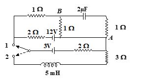
For the circuit arrangement as shown in the figure. Initially, the switch is in position 1 and the circuit is in the steady state condition
Q.8
Find the charge on the capacitor.
If the switch is now put in the position 2
(a) \displaystyle 5\mu C
(b) \displaystyle 4\mu C
(c) \displaystyle 8\mu C
(d)none
Ans : (a)
Q.9
Find the steady current in 3W resistor.
(a) 0.9A
(b) 1.2A
(c) 0.6A
(d) 0.3A
Ans : (c)
Q.10
Find the time in which the current in 3W resistor rises to half of its steady state value.
(a) 0.301ms
(b) 0.693ms
(c) 0.245ms
(d) 0.701ms
Ans : (b)
Q.11
Calculate the maximum energy stored in the inductor.
(a) 0.9mJ
(b) 0.5mJ
(c) 1.9mJ
(d) 2.3mJ
Ans : (a)
Comprehension (Q.12 to Q.13)
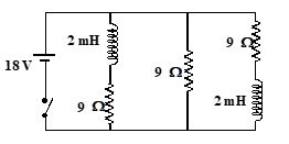
Consider the circuit shown in figure, what is the current through the battery
Q.12
just after the switch is closed
(a) 2A (b) 6A (c) 3A (d) 7A
Ans : (a)
Q.13
long after the switch has been closed
(a) 2A (b) 6A (c) 3A (d) 7A
Ans : (b)
Comprehension (Q.14 to Q.16)
A 3.56 H inductor is placed in series with a 12.8 W resistor, and an emf of 3.24 V is then suddenly applied across the RL combination.
Q.14
At 0.278 s after the emf is applied the rate at which energy is being delivered by the battery must be
(a) 618 mW (b) 328 mW (c) 191 mW (d) 518 mW
Ans : (d)
Q.15
At 0.278 s, the rate at which energy appearing as thermal energy in the resistor must be
(a) 618 mW (b) 328 mW (c) 191 mW (d) 518 mW
Ans : (b)
Q.16
At 0.278 s, the rate at which energy is being stored in the magnetic field must be
(a) 618 mW (b) 3 28 mW (c) 91 mW (d) 518 mW
Ans : (c)
Comprehension (Q.17 to Q.18)
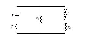
An inductor of inductance L = 400 mH and resistors of resistances R1 = 2W and R2 = 2 W are connected to a battery of emf E = 12 V as shown in the figure. The internal resistance of the battery is negligible. The switch S is closed at time t = 0.
Q.17
What is the potential drop across L as a function of time?
(a) \displaystyle 12{{e}^{{-5t}}} ,
(b) \displaystyle 6{{e}^{{-5t}}}
(c) \displaystyle 6{{e}^{{10t}}} ,
(d) none
Ans : (a)
Q.18
After the steady state is reached, the switch is opened. What is the magnitude of current through R1 as a function of time?
(a) \displaystyle 12{{e}^{{10t}}}
(b) \displaystyle 10-12{{e}^{{10t}}}
(c) \displaystyle 6{{e}^{{10t}}}
(d) \displaystyle 16{{e}^{{-5t}}}
Ans : (c)

