Video Lecture
Theory For Making Notes
Mutual Induction
It is the phenomena of inducing emf in a coil or closed loop by passing a varying current in the neighboring coil or loop.
Actually a changing current in one circuit causes a changing magnetic flux and when this changing magnetic flux passes through the second circuit an induced emf in that.
in the diagram the loop conected to the battery is called primary and the other one is called secondary. Let \displaystyle {{N}_{1}} and \displaystyle {{N}_{2}} be the number of turns in the primary and secondary loops. If \displaystyle {{phi}_{2}} be the flux linked with a single turn of secondary then the net or total flux linked with the secondary is equal to \displaystyle {{N}_{2}}{{\phi }_{2}}
This net flux linked with secondary is proportional to current in the first circuit.
hence \displaystyle {{N}_{2}}{{\phi }_{2}}\propto {{I}_{1}}
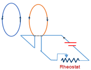
i.e. \displaystyle {{N}_{2}}{{\phi }_{2}}=\text{ }M{{i}_{1}}
The proportionality factor is called mutual inductance and is denoted by M
hence M = \frac{{{{N}_{2}}{{\phi }_{2}}}}{{{{i}_{1}}}}=\frac{{{{N}_{1}}{{\phi }_{1}}}}{{{{i}_{2}}}}
or, \displaystyle {{e}_{2}}= -M \frac{{d{{i}_{1}}}}{{dt}} and \displaystyle {{e}_{1}}= -M \frac{{d{{i}_{2}}}}{{dt}}
Mutual Inductance for a system of two coaxial solenoids:
Consider two long co-axial solenoids each of length \displaystyle l. Denote the radius of the inner solenoid by \displaystyle {{r}_{1}} and the number of turns per unit length by \displaystyle {{n}_{1}}. The corresponding quantities for the outer solenoid are \displaystyle {{r}_{2}} and \displaystyle {{n}_{2}}, respectively. Let \displaystyle {{N}_{1}} and \displaystyle {{N}_{2}} be the total number of turns of coils \displaystyle {{S}_{1}} and \displaystyle {{S}_{2}}, respectively.
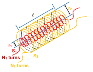
When a current \displaystyle {{I}_{2}} is set up through \displaystyle {{S}_{2}}, in turn it sets up a magnetic flux through \displaystyle {{S}_{1}}. Denote it by \displaystyle {{\phi }_{1}}. The corresponding flux linkage with solenoid \displaystyle {{S}_{1}} is
\displaystyle {{N}_{1}}{{\phi }_{1}}=\text{ }{{M}_{{12}}}{{I}_{2}} …(1)
\displaystyle {{M}_{{12}}} is called the mutual inductance of solenoid \displaystyle {{S}_{1}} with respect to solenoid \displaystyle {{S}_{2}}. It is also referred to as the coefficient of mutual induction.
Let us calculate \displaystyle {{M}_{{12}}}. The magnetic field due to the current \displaystyle {{I}_{2}}. in \displaystyle {{S}_{2}}. is \displaystyle {{\mu }_{0}}{{n}_{2}}{{I}_{2}}.
The resulting flux linkage with coil \displaystyle {{S}_{1}} is
\displaystyle {{N}_{1}}{{\phi }_{1}}=\text{ }({{n}_{1}}l) ( (\pi r_{1}^{2})({{\mu }_{0}}{{n}_{2}}{{I}_{2}})
\displaystyle {{N}_{1}}{{\phi }_{1}}=\text{ }({{n}_{1}}l)= {{\mu }_{0}}{{n}_{1}}{{n}_{2}}\pi r_{1}^{2}\ell {{I}_{2}} …(2)
where \displaystyle {{n}_{1}}l is the total number of turns in
solenoid \displaystyle {{S}_{1}}l. Thus from (1) and (2)
\displaystyle {{M}_{{12}}}={{\mu }_{0}}{{n}_{1}}{{n}_{2}}\pi r_{1}^{2}l …(3)
Note that we have neglected the edge effect and considered the magnetic field \displaystyle {{\mu }_{0}}{{n}_{2}}{{I}_{2}}to be uniform throughout the length and width of the solenoid \displaystyle {{S}_{2}}. This a good approximation keeping in mind that the solenoid is long and \displaystyle l>>{{r}_{2}}.
We consider the reverse case. A current \displaystyle {{I}_{1}} is passed through the solenoid \displaystyle {{S}_{1}} and the flux linkage with coil \displaystyle {{S}_{2}} is
\displaystyle {{N}_{2}}{{\phi }_{2}}=\text{ }{{M}_{{21}}}{{I}_{1}} …(4)
\displaystyle {{M}_{{21}}} is called the mutual inductance of solenoid \displaystyle {{S}_{2}} with respect to solenoid \displaystyle {{S}_{1}}.
The flux due to the current \displaystyle {{I}_{1}} in \displaystyle {{S}_{1}} can be assumed to be confined solely inside \displaystyle {{S}_{1}} since the solenoids are very long. Thus, flux linkage with solenoid \displaystyle {{S}_{2}} is
\displaystyle {{N}_{2}}{{\phi }_{2}}=\text{ }({{n}_{2}}l) (\pi r_{1}^{2}) \displaystyle ({{\mu }_{0}}{{n}_{1}}{{I}_{1}}) …(5)
where \displaystyle {{n}_{1}}lis the total number of turns of \displaystyle {{S}_{2}}. From equation (4) and (5)
{{M}_{{21}}}={{\mu }_{0}}{{n}_{1}}{{n}_{2}}\pi r_{1}^{2}\ell …(6)
using equation (3) and (6), we get
\displaystyle {{M}_{{12}}}=\text{ }{{M}_{{21}}}=\text{ }M (say)
We have demonstrated this equality for long co-axial solenoids. However, the relation is a general one. Note that if the inner solenoid were much shorter than (even if placed well inside) the outer solenoid, it would be extremely difficult to calculate the flux linkage with the outer solenoid as the magnetic field due to the inner solenoid would vary across the length as well as across sections of the outer solenoid. Therefore, the calculation of \displaystyle {{M}_{{21}}} would also be extremely difficult in this case.
We have explained the above example with air as the medium within the solenoids. Instead, if a medium of relative permeability \displaystyle {{\mu }_{r}} had been present, the mutual inductance would be
\displaystyle M\text{ }={{\mu }_{r}}{{\mu }_{0}}{{n}_{1}}{{n}_{2}}\pi r_{1}^{2}\ell
It is also important to know that the mutual inductance of a pair of coils, solenoids, etc., depends on their separation as well as their relative orientation.
Illustration
Is it possible to have mutual inductance without self- inductance? What about self inductance without mutual inductance?
Solution
No it is not possible to have mutual induction without self-induction. But self-induction is possible without mutual induction.
Illustration
A solenoid \displaystyle {{S}_{1}} is placed inside another solenoid S2 . The radii of the inner and the outer solenoids are \displaystyle {{r}_{1}} and \displaystyle {{r}_{2}} respectively and the number of turns per unit length are \displaystyle {{n}_{1}} and \displaystyle {{n}_{2}} respectively. if l be the length of each solenoid, calculate the mutual inductance between them.
Solution
Suppose a current i is passed through the inner solenoid \displaystyle {{S}_{1}}. A magnetic field \displaystyle B\text{ }={{\mu }_{0}}{{n}_{1}}i is produced inside \displaystyle {{S}_{1}} whereas the field outside it is zero. The flux \displaystyle {{\phi}_{2}} through each turn of \displaystyle {{S}_{2}} can be calculated by the formula
\displaystyle \begin{array}{l}{{\phi}_{2}} =B\times A\\\Rightarrow {{\phi}_{2}} =B\pi {{r}_{1}}^{2}\\\Rightarrow {{\phi}_{2}} =\text{ }({{\mu }_{0}}{{n}_{1}}i)\pi {{r}_{1}}^{2}\end{array}
Also the total flux through all the turns in a length \displaystyle lof \displaystyle {{S}_{2}} can be written as,
\displaystyle {{\phi }_{2}}=MI~
Thus, \displaystyle M=\frac{{{{\phi }_{2}}}}{I}
on sbstituting the value of \displaystyle {{\phi}_{2}} we get M = \displaystyle {{\mu }_{0}}{{n}_{1}}{{n}_{2}}\pi r_{1}^{2}\ell
Illustration
A very small square loop of side ‘l’ is placed inside a large square loop of wire of side L as shown loops are coplanar.
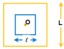
What is the mutual inductance of system? (A) zero. (B) \frac{{{{\mu }_{0}}{{\ell }^{2}}}}{{\pi L}} (C) \frac{{{{\mu }_{0}}4\sqrt{2}{{\ell }^{2}}}}{{\pi L}} (D) \frac{{{{\mu }_{0}}2\sqrt{2}{{\ell }^{2}}}}{{\pi L}}
|
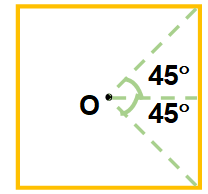
Also r = L/2
B0 = \frac{{{{\mu }_{0}}I}}{{\pi L}}\left( {\frac{2}{{\sqrt{2}}}} \right) = \frac{{{{\mu }_{0}}I2\sqrt{2}}}{{\pi L}}
\displaystyle \phi =\text{ }{{B}_{0}}{{l}^{2}}= \frac{{{{\mu }_{0}}I2\sqrt{2}}}{{\pi L}}{{\ell }^{2}}
Also flux through smaller loop can be written as \displaystyle \phi = MI
hence M = \frac{{{{\mu }_{0}}2\sqrt{2}{{\ell }^{2}}}}{{\pi L}}
hence D option is correct
Transformer
It is a device which increases or decreases the alternating voltage in ac circuits through mutual induction.
It consists of two coils primary (Input) and secondary (output) wound on the same core. The alternating current passing through the primary creates a continuously varying magnetic flux through the core. This changing flux induces an alternating emf in the secondary.
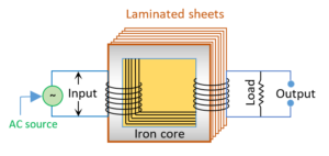
Few main points to be noted:
(1) Transformer works on ac only and not on dc.
(2) It can increase or decrease either voltage or current but not both simultaneously.
(3) Transformer does not change the frequency of input ac.
(4) The primary and secondary coils are linked magnetically.
(5) The flux per turn of each coil must be same i.e. {{\phi }_{S}}={{\phi }_{P}} hence -\frac{{d{{\phi }_{S}}}}{{dt}}=-\frac{{d{{\phi }_{P}}}}{{dt}}.
(6) If \displaystyle {{N}_{p}} = number of turns in primary, \displaystyle {{N}_{s}} = number of turns in secondary, \displaystyle {{V}_{p}} = applied (input) voltage to primary, \displaystyle {{V}_{s}} = Voltage across secondary (load voltage or output), \displaystyle {{e}_{p}} = induced emf in primary ; \displaystyle {{e}_{s}} = induced emf in secondary, \displaystyle \phi = flux linked with primary as well as secondary, \displaystyle {{i}_{p}} = current in primary; \displaystyle {{i}_{s}} = current in secondary (or load current)
As in an ideal transformer there is no loss of power i.e. {{P}_{{out}}}={{P}_{{in}}} so {{V}_{S}}.{{i}_{S}}={{V}_{P}}.{{i}_{P}} and {{V}_{P}}\approx {{e}_{P}}, {{V}_{S}}\approx {{e}_{S}}.
Hence \frac{{{{e}_{s}}}}{{{{e}_{p}}}}=\frac{{{{N}_{s}}}}{{{{N}_{p}}}}=\frac{{{{i}_{p}}}}{{{{i}_{s}}}}=k where k is called Transformation ratio (or turn ratio)
Efficiency of transformer ( \displaystyle \eta) : Efficiency is defined as the ratio of output power and input power
i.e. \eta =\frac{{{{P}_{{out}}}}}{{{{P}_{{in}}}}}=\frac{{{{V}_{S}}.{{i}_{S}}}}{{{{V}_{P}}.{{i}_{P}}}}
For an ideal transformer \displaystyle {{P}_{out}} = \displaystyle {{P}_{in}} so \eta \,=100\% (But efficiency of practical transformer lies between 70% – 90%)
For practical transformer {{P}_{{in}}}={{P}_{{out}}}+{{P}_{{loss}}}
so in percentage the efficiency can be given as:
\eta \,=\frac{{{{P}_{{out}}}}}{{{{P}_{{in}}}}}\times 100=\frac{{{{P}_{{out}}}}}{{({{P}_{{out}}}+{{P}_{loss}})}}\times 100=\frac{{({{P}_{{in}}}-{{P}_{loss}})}}{{{{P}_{{in}}}}}\times 100
Losses in transformer :
In transformers some power is always lost due to, heating effect, flux leakage eddy currents, hysteresis and humming.
(i) Cu loss ( (H={{i}^{2}}R).) : When current flows through the transformer windings some power is wasted in the form of heat (H={{i}^{2}}Rt).To minimize this loss windings are made of thick Cu wires (To reduce resistance)
(ii) Eddy current loss : Some electrical power is wasted in the form of heat due to eddy currents, induced in core, to minimize this loss transformers core are laminated and silicon is added to the core material as it increases the resistivity. The material of the core is then called silicon-iron (steel).
(iii) Hystersis loss : The alternating current flowing through the coils magnetises and demagnetises the iron core again and again. Therefore, during each cycle of magnetisation, some energy is lost due to hysteresis. However, the loss of energy can be minimised by selecting the material of core, which has a narrow hysterisis loop. Therefore core of transformer is made of soft iron. Now a days it is made of “Permalloy” (Fe-22%, Ni-78%).
(iv) Magnetic flux leakage : Magnetic flux produced in the primary winding is not completely linked with secondary because few magnetic lines of force complete their path in air only. To minimize this loss secondary winding is kept inside the primary winding.
(v) Humming losses : Due to the passage of alternating current, the core of the transformer starts vibrating and produces humming sound. Thus, some part (may be very small) of the electrical energy is wasted in the form of humming sounds produced by the vibrating core of the transformer.
Uses of transformer :
A transformer is used in almost all ac operations e.g.
(i) In voltage regulators for TV, refrigerator, computer, air conditioner etc.
(ii) In the induction furnaces.
(iii) Step down transformer is used for welding purposes.
(iv) In the transmission of ac over long distance.
(v) Step down and step up transformers are used in electrical power distribution.
(vi) Audio frequency transformers are used in radiography, television, radio, telephone etc.
(vii) Radio frequency transformers are used in radio communication.
(viii) Transformers are also used in impedance matching.
Practice Questions (Basic Level)
Q.1
The mutual inductance between a pair of coils each of N turns is M. If a current i in the first coil is brought to zero in time t, then, average emf induced in the second coil is
(a) \frac{{Mi}}{t}
(b) \frac{{NMi}}{t}
(c) \frac{{Mi}}{{Nt}}
(d) \frac{{Mt}}{{iN}}
Ans. (a)
Q.2
Two coils X and Y are placed in a circuit such that a current changes by 2 A in coil X and the magnetic flux change of 0.4 weber occur in Y. The value of mutual inductance of the coils is
(a) 0.2 henry
(b) 5 henry
(c) 0.8 henry
(d) 2 henry
Ans. (a)
Q.3
If two coils of self inductance 4H and 16H are wound on the same iron core. The coefficient of mutual inductance for them will be
(a) 8H (b) 10H (c) 20H (d) 164H
Ans. (a)
Q.4
A small square loop of wire of side l is placed inside a large square loop of wire of side
L( L >> l). The loops are co-planar and their centres coincide. The mutual inductance of the system is proportional to
(a) l/L (b) l2/L (c) L/l (d) L2/l
Ans. (b)
5.
An ideal transformer has 500 and 5000 turns in primary and secondary winding respectively. If the primary voltage is connected to a 6 V battery then the secondary voltage is
(a) 0
(b) 60 V
(c) 0.6 V
(d) 6.0 V
Ans (a)
6.
A step-down transformer transforms a supply line voltage of 2200 volt into 220 volt. The primary coil has 5000 turns. The number of turns in the secondary are
(a) 5000
(b) 550
(c) 500
(d) 450
Ans (b)
7.
A transformer
(a) transforms energy
(b) transforms frequency
(c) transforms voltage
(d) generates e.m.f.
Ans (c)
8.
In a transformer, the number of turns of primary coil and secondary coil are 5 and 4 respectively. If 240 V is applied on the primary coil, then the ratio of current in primary and secondary coil is
(a) 4 : 5
(b) 5 : 4
(c) 5 : 9
(d) 9 : 5
Ans (A)
9.
The number of turns in the primary and secondary turns of a transformer are 1000 and 3000 respectively. If 80 V AC is supplied to the primary coil of the transformer, then the potential difference per turn of the secondary coil would be
(a) 240 V
(b) 2400 V
(c) 0.24 V
(d) 0.08 V
Ans (d)
10.
A transformer has 200 windings in the primary and 400 windings in the secondary. The primary is connected to an ac supply of 110 V a current of 10 A flows in it. The voltage across the secondary and the current in it, respectively, are
(a) 55V, 20 A
(b) 440 V, 5A
(c) 220 V, 10A
(d) 220V, 5A
Ans (d)
Practice Questions (JEE Main Level)
Q.1
The diagram shows a solenoid carrying time varying current I={{I}_{0}}t. On the axis of this solenoid a ring has been placed. The mutual inductance of the ring and the solenoid is M and the self inductance of the ring is L. If the resistance of the ring is R then maximum current which can flow through the ring is
(a) \frac{{\left( {2M+L} \right){{I}_{0}}}}{R}
(b) \frac{{M{{I}_{0}}}}{R}
(c) \frac{{\left( {2M-L} \right){{I}_{0}}}}{R}
(d) \frac{{\left( {M+L} \right){{I}_{0}}}}{R}

Ans. (b)
Q.2
A dynamo dissipates 20 watt when it supplies a current of 4 amp through it. If the terminal potential difference is 220 volt, then the emf produced is
(a) 220V (b) 225V (c) 215V (d) 300V
Ans. (b)
Q.3
Two coils of inductances L1 and L2 are linked such that their mutual inductance is M
(a) M={{L}_{1}}+{{L}_{2}}
(b) M=\frac{1}{2}({{L}_{1}}+{{L}_{2}})
(c) The maximum value of M is (L1 + L2)
(d) The maximum value of M is \sqrt{{{{L}_{1}}{{L}_{2}}}}
Ans. (d)
Q.4
If turn ratio is 3 : 1 then V0 is equal to
(a) 5 V (b) 45 V (c) 15 V (d) 0

Ans. (d)
Q.5
A transformer has turn ratio 2 and input power 3600 W. Load current is 20 A. Efficiency . Find the internal resistance
(a) 9\,\Omega
(b) 1.9\,\Omega
(c) 1.2\,\Omega
(d) 0.9\,\Omega
Ans. (d)
Practice Questions (JEE Advance Level)
Q.1
A small square loop of wire of side l is placed inside a large square loop of wire of side L (>>l). The loops are coplanar and their centers coincide. The mutual inductance of the system must be
(a) 2\sqrt{2}\frac{{{{\mu }_{o}}{{l}^{2}}}}{{\pi {{L}^{2}}}}
(b) 2\sqrt{2}\frac{{{{\mu }_{o}}{{l}^{2}}}}{{\pi L}}
(c) 2\frac{{{{\mu }_{o}}{{l}^{2}}}}{{\pi L}}
(d) \frac{{{{\mu }_{o}}{{l}^{2}}}}{{\sqrt{2}\pi L}}
Ans : (b)
Q.2
A long solenoid having 200 turns per cm carries a current of 1.5 amp. At the center of it is placed a 100 turns of cross-sectional area 3.14 ´ 10-4 m2 having its axis parallel to the field produced by the solenoid. When the direction of current in the solenoid is reversed within 0.05 s, the emf induced in the coil must be
(a) 0.048A (b) 1.45A (c) 0.48A (d) 2.42A
Ans : (a)
Q.3
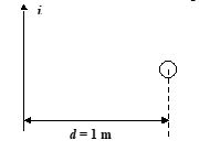
A current i = 33.6 (1 + 2t) mA increases at a steady rate in a long straight wire. A small circular loop of radius a = 10-3 m has its plane parallel to the wire and is placed at a distance of 1 m from the wire. The resistance of the loop is 8.4 ´ 10-4 W. The magnitude of induced current in the loop is \displaystyle k\times {{10}^{{-11}}}A. Where k is
(a) 2 (b) 3 (c) 5 (d) 8
Ans. (c)
Q.4
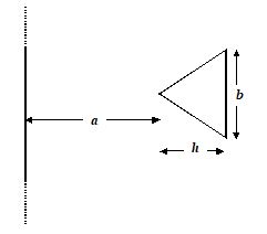
A very long conductor and an isosceles triangular conductor lie in a plane and separated from each other as shown in the figure. a = 10 cm; b = 20 cm; h = 10 cm
If current in the straight wire is increasing at a rate of 2 A/s, find the magnitude of current in the triangular wire. Diameter of the wire cross-section d = 1 mm. Resistivity of the wire, r = 1.8 ´ 10-8 Wm.
(a) 2 \displaystyle \mu A
(b) 1.67 \displaystyle \mu A
(c) 3.7 \displaystyle \mu A
(d) 2.2 \displaystyle \mu A
Ans. (d)
Q.5
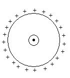
A charge Q is uniformly distributed over a non-conducting ring of radius R. The ring is rotated clockwise from rest with a constant angular acceleration a. A conducting ring of radius ‘a’ is placed concentrically at the centre of the charged ring (a << R).
If resistance of the small ring is ‘r’, then the value of induced current in it must be
(a) \frac{{{{\mu }_{o}}Q{{a}^{2}}\alpha }}{{2Rr}}
(b) \frac{{3{{\mu }_{o}}Q{{a}^{2}}\alpha }}{{2Rr}}
(c) \displaystyle \frac{{{{\mu }_{o}}Qa\alpha }}{{4{{R}^{2}}r}}
(d) \frac{{{{\mu }_{o}}Q{{a}^{2}}\alpha }}{{4Rr}}
Ans. (d)
Q.6
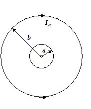
A very small loop of radius a is placed at the centre of a very large loop of radius b as shown in the figure. The large loop carries a constant current Io and is kept fixed in space. The small loop is rotated about its diametric axis with angular velocity w. If the resistance of the small loop is R and the self inductance is negligible.
Find the torque required to rotate the small loop.
(a) {{\left[ {\frac{{{{\mu }_{o}}\pi {{b}^{2}}{{I}_{o}}\omega }}{{2a}}} \right]}^{2}}\,\left( {\frac{\omega }{R}} \right)\,{{\sin }^{2}}\omega t
(b) {{\left[ {\frac{{{{\mu }_{o}}\pi {{a}^{{}}}{{I}_{o}}\omega }}{{3{{b}^{3}}}}} \right]}^{2}}\,\left( {\frac{\omega }{R}} \right)\,{{\sin }^{2}}\omega t
(c) {{\left[ {\frac{{{{\mu }_{o}}\pi {{a}^{2}}{{I}_{o}}\omega }}{{2b}}} \right]}^{2}}\,\left( {\frac{\omega }{R}} \right)\,{{\sin }^{2}}\omega t
(d) {{\left[ {\frac{{{{\mu }_{o}}\pi {{a}^{2}}{{I}_{o}}\omega }}{{2b}}} \right]}^{2}}\,\,{{\sin }^{2}}\omega t
Ans. (c)
Comprehension ( Q.7 to Q.8)

An equilateral triangular frame PQR of mass M and side a is at rest is under the influence of horizontal magnetic field B and gravitational field as shown in the figure.
Q.7
Find the magnitude and direction of current in the frame so that the frame remains at rest.
(a) \frac{{Mg}}{{aB}}
(b) \frac{{2Mg}}{{aB}}
(c) \frac{{Mg}}{{2aB}}
(d) \frac{{Mg}}{{{{a}^{2}}B}}
Ans : (b)
Q.8
If the frame is slightly displaced in its plane perpendicular to PQ, show that its motion is simple harmonic and find its period of oscillation.
[Neglect EMF induced due to motion of the loop]
(a) \pi \sqrt{{\frac{{\sqrt{3}\,\,a}}{g}}}
(b) \pi \sqrt{{\frac{{3\,\,a}}{g}}}
(c) 2\pi \sqrt{{\frac{{\sqrt{3}\,\,a}}{g}}}
(d) \frac{\pi }{2}\sqrt{{\frac{{\sqrt{3}\,\,a}}{g}}}
Ans : (a)
