Video Lecture
Motional EMF in a Moving Conductor (By Area Method)
If conducting rod moves on two parallel conducting rails as shown in following figure then phenomenon of induced emf can also be understand by the concept of generated area (The area swept of conductor in magnetic field, during it’s motion)
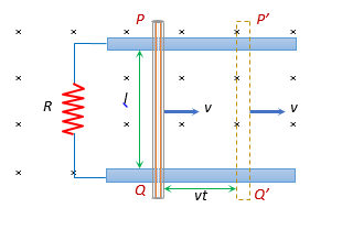
As shown in figure in time dt distance travelled by conductor \displaystyle =v.dt
Area swept in time dt is \displaystyle \left( {dA} \right)\text{ }=\text{ }area\left( {PP’Q’Q} \right)=lv.dt.
Hence induced emf E=-\frac{{d\phi }}{{dt}}=-\frac{{d(BA)}}{{dt}}=-B\frac{{dA}}{{dt}},
on putting \displaystyle dA\text{ }=lv.dt we get induced emf finally
Therefore induced emf is E=-Blv
Illustration
A metal rod of length l slides at constant velocity v on conducting rails, placed in a uniform and constant magnetic field B perpendicular to the plane of the rails as shown in figure. A resistance R is connected between the two ends of the rail.
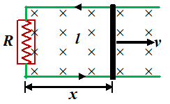
(a) Find the current in the resistor
(b) Find the power dissipated in the resistor
(c) Find the mechanical power needed to pull the rod.
Solution
In this case flux varies due to the change of area. Let x be the instantaneous distance moved by the rod, then the flux through the area enclosed is
\displaystyle ~{{\phi }_{B}}=BA=Blx
The magnitude of the induced emf is
|E| = \frac{{d{{\phi }_{B}}}}{{dt}}\,=\,B\ell \,\frac{{dx}}{{dt}}\,=\,B\ell v
The flux is increasing because the area is increasing. The induced emf opposes the increase in flux, which means that the induced magnetic field is opposite to the external field. Thus, the induced current in the circuit is anticlockwise.
The magnitude of the current is
\displaystyle I=\frac{E}{R}\,\,=\,\frac{{B\ell v}}{R}
(b) The electric power dissipated in the resistor is
\displaystyle {{P}_{{elec}}}~={{I}^{2}}R = {{\left( {\frac{{B\ell v}}{R}} \right)}^{2}}R …(i)
(c) Because of the induced current flowing in it, the rod experiences a force \displaystyle \vec{F}=I(\vec{l}\times \vec{B}) due to the external field. This force \displaystyle \vec{F} is directed opposite to v. In order to move the rod at constant velocity an external force Fext = I\,lB must be applied to the right.
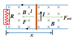
The mechanical power supplied by the external agent is
\displaystyle {{P}_{{mech}}} = \overset{\to }{\mathop{{{{F}_{{ext}}}}}}\,\,.\,\overset{\to }{\mathop{v}}\,\,= \frac{{{{{\left( {B\ell v} \right)}}^{2}}}}{R} …(ii)
Comparing equation (i) and (ii) we get
\displaystyle {{P}_{{mech}}}={{P}_{{elec}}} (System is obeying Law of Conservation Of Energy)
Illustration
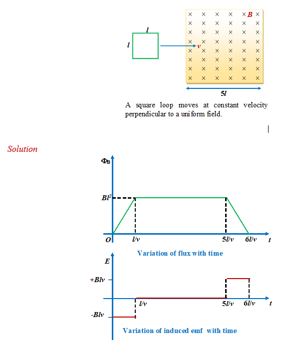
A square loop of side l moves at constant velocity v perpendicular to a uniform magnetic field as shown in the figure Starting at the time at which it enters the field until it leaves the field, make plots of the variation in the flux through the loop and the emf induced in it as functions of time.
MECHANISM OF THE INDUCED EMF
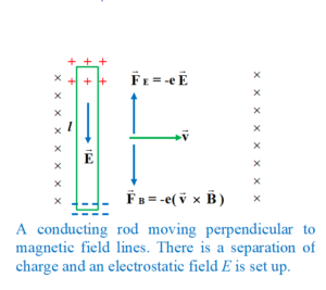
When a conducting rod of length l moves at constant velocity v perpendicular to a uniform magnetic field \vec{B} (as shown in figure given below) an electron experiences a magnetic force
\displaystyle \vec{F}=-e(\vec{v}\times \vec{B}) directed downward along the rod. As a result, electron migrates to the lower end of the rod and leave unbalanced positive charge at the top. This redistribution of charge sets up an electrostatic field \displaystyle {\vec{E}} directed downward.
In the absence of any external circuit an equilibrium is established between the electric and magnetic forces.
Thus, \displaystyle {{{\vec{F}}}_{E}}+{{{\vec{F}}}_{B}}=0
or \displaystyle \vec{E}+(\vec{v}\times \vec{B})=0
The action of the magnetic force may be considered similar to the action of a certain electric field (opposing the Coulomb field) of magnitude
\vec{E}*= \frac{{{{{\vec{F}}}_{m}}}}{q}\,=\,\vec{v}\,\times \,\vec{B} (5)
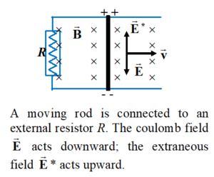
Since the field is not due to the separation of charges, but to non-electrostatic forces (in this case magnetic), therefore, it is called an extraneous field. Unlike coulomb field it is directed from negative to positive charges.
When the moving rod is connected to an external resistor (shown in figure given below), the following points are observed.
(i) The potential difference between the ends of the conductor is less than when the circuit was open.
(ii)The strength of the extraneous field \vec{E}* remain unchanged because it depends only on \vec{v} and \vec{B}.
The direction of induced current coincides with the direction of motion of positive charges i.e. with the resultant electric field.
In the external part of the circuit, positive charges flow from A to B. Thus, the work done by the net external field is
\displaystyle {{W}_{{ext}}}=q({{\phi }_{A}}-~{{\phi }_{B}})
In the internal part of the circuit, positive charges flow from B to A. The work done in the internal part of the circuit is
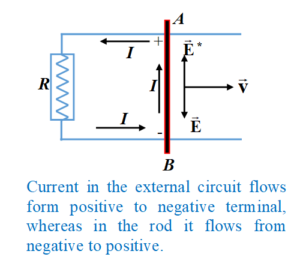
\displaystyle {{W}_{{int}}}=\int{q}({{{\vec{E}}}^{*}}-\vec{E}).d\vec{l}~
or \displaystyle {{W}_{{int}}}=q\int{{(\vec{v}\times \vec{B}).d\vec{l}-q\int{{\vec{E}.d\vec{l}}}}}
or \displaystyle {{W}_{{int}}}=q\int{{(\vec{v}\times \vec{B}).d\vec{l}-q({{\phi }_{A}}-{{\phi }_{B}})}}
Hence the total work done is
\displaystyle W={{W}_{{ext}}}+~{{W}_{{int}}}=q\int{{(\vec{v}\times \vec{B}).d\vec{l}}} (6)
The net work done in moving a charge along a closed circuit is equal to the work done by non-electrostatic forces.
Being a conservative force an electrostatic force does no work along a closed path.
The electromotive force is defined as the ratio of the work done in moving a charge along a closed circuit, to the magnitude of charge.
\displaystyle E=\frac{W}{q}=\int{{(\vec{v}\times \vec{B}).d\vec{l}}}
Induced EMF in a Rotating Conductor
Consider a conducting rod of length L rotates about one of its ends with a constant angular
speed \displaystyle \omega . The plane of rotation of the rod is perpendicular to uniform magnetic field B.
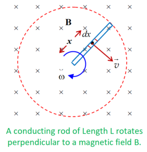
Imagine a small element of length dx at a distance x from centre of rotation. The velocity of
this point is
\displaystyle \,\,v=\omega x
Emf induced in this small length is dE = -Bdx.v ( we know E= -Blv)
Hence dE = -Bdx.( \displaystyle \omega x)
Hence emf induced in the entire conductor can be found by integration
\displaystyle E=-Bv\int\limits_{0}^{L}{{x\,dx}}
Hence \displaystyle E=\frac{1}{2}\omega B{{L}^{2}}
Practice Questions (Basic Level)
Q.1
A copper rod of length l is rotated about one end perpendicular to the uniform magnetic field B with constant angular velocity w. The induced emf between two ends is –
(a) \frac{3}{2}Bwl2
(b) Bwl2
(c) 2Bwl2
(d) \frac{1}{2}Bwl2
Ans : (d)
Q.2
The wire AB slides with velocity v and remains in contact with fixed rails. If the wire AB is replaced by a semicircular arc, the magnitude of induced current will
(a) increase
(b) remain the same
(c) decrease
(d) depends on the orientation of arc

Ans. (b)
Q.3
A rod of length l rotates with a uniform angular velocity w about its perpendicular bisector. A uniform magnetic field B exists parallel to the axis of the rotation. The potential difference between the two ends of the rod is
(a) zero
(b) \frac{1}{2}Bl{{\omega }^{2}}
(c) Bl{{\omega }^{2}}
(d) 2Bl{{\omega }^{2}}
Ans : (a)
Q.4
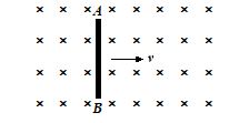
A rod AB moves with a uniform velocity v An a uniform magnetic field as shown in figure.
(a) The rod becomes electrically charged.
(b) The end A becomes positively charged
(c) The end B becomes positively charged.
(d) The rod becomes hot because of Joule heating. A
Ans. (b)
Q.5
A metal rod of length \vec{l} is moved with a constant velocity \vec{v} in a magnetic field \vec{B}. A potential difference appears across the two ends when
(a) \vec{v}||\vec{l}
(b) \vec{v}||\vec{B}
(c) \vec{l}||\vec{B}
(d) none of these
Ans: (d)
Practice Questions (JEE Main Level)
Q.1
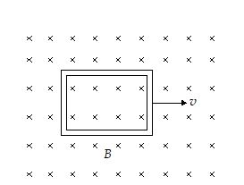
A conducting square loop of side L and resistance R moves in its plane with a uniform velocity v perpendicular to one of its sides. A magnetic induction B, constant in time and space, pointing perpendicular and into the plane of the loop exists everywhere. The current induced in the loop is
(a) BLv/R clockwise
(b) 2BLv/R anticlockwise
(c) BLv/R anticlockwise
(d) zero
Ans. (c)
Q.2
A rod is rotating with a constant angular velocity w about point O (its center) in a magnetic field B as shown.
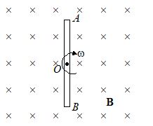
Which of the following figure correctly shows the distribution of charge inside the rod
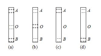
Ans. (a)
Q.3
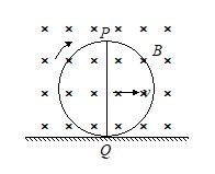
A conducting straight wire PQ of length l is fixed along a diameter of a non-conducting ring as shown in the figure. The ring is given a pure rolling motion on a horizontal surface such that its center of mass has a velocity v. There exists a uniform horizontal magnetic field B in horizontal direction perpendicular to the plane of ring. The magnitude of induced emf in the wire PQ at the position shown in the figure will be
(a) Bvl (b) 2Bvl (c) 3Bvl/2 (d) zero
Ans. (a)
Q.4
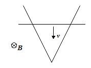
A wire is bent in form of a V shape and placed in a horizontal plane. There exist a uniform magnetic field B perpendicular to the plane of the wire. A uniform conducting rod starts sliding over the V shaped wire with a constant speed v as shown in the figure. If the wire has no resistance, the current in the rod will
(a) increase with time
(b) decrease with time
(c) remain constant
(d) always be zero
Ans. (c)
Q.5
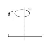
A conducting rod of length 2l is rotating with constant angular speed w about its perpendicular bisector. A uniform magnetic field exists parallel to the axis of rotation. The emf induced between two ends of the rod is
(a) Bwl2
(b) \frac{1}{2}Bwl2
(c) \frac{1}{8}Bwl2
(d) zero
Ans. (d)
Q.6
A capacitance C is connected to a conducting rod of length l moving with a velocity v in a transverse magnetic field B then the charge developed in the
(a) zero
(b) BlvC
(c) \frac{1}{8}
(d) \frac{{BlvC}}{3}

Ans. (b)
Q.7
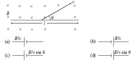
A rod of length l is moved with a velocity v in a magnetic field B as shown in figure, the equivalent electrical circuit is
Ans. (c)
Q.8
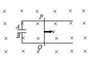
A conducting rod PQ of length L = 1.0 m is moving with a uniform speed v = 2.0m/s in a uniform magnetic field B = 4.0 T direction into the paper. A capacitor of capacity C = 10 mF is connected as shown in figure. Then
(a) {{q}_{A}}=+80\mu C and {{q}_{B}}=-80\mu C
(b) {{q}_{A}}=-80\mu C and {{q}_{B}}=+80\mu C
(c) {{q}_{A}}=0={{q}_{B}}
(d) charge stored in the capacitor increases exponentially with time
Ans. (a)
Q.9
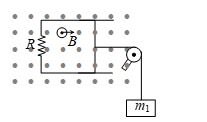
A rod of length l, negligible resistance and mass m slides on two horizontal frictionless rails of negligible resistance by hanging a block of mass m1 by the help of insulating massless string passing through fixed massless pulley (as shown). If a constant magnetic field B acts upwards perpendicular to the plane of the figure, the terminal velocity of hanging mass is
(a) \frac{{{{m}_{1}}gR}}{{{{B}^{2}}{{l}^{2}}}} upward
(b) \frac{{{{m}_{1}}gR}}{{{{B}^{2}}{{l}^{2}}}} downward
(c) \frac{{{{m}_{1}}gR}}{{2{{B}^{2}}{{l}^{2}}}}downward
(d) \frac{{{{m}_{1}}gR}}{{{{B}^{2}}l}} downward
Ans. (b)
Q.10
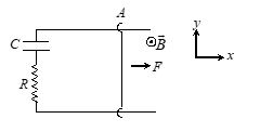
A conducting rod AB moves parallel to x-axis in the x–y plane. A uniform magnetic field B pointing normally out of the plane exists throughout the region. A force F acts perpendicular to the rod, so that the rod moves with uniform velocity v. The force F is given by (neglect resistance of all the wires)
(a) \frac{{v{{B}^{2}}{{l}^{2}}}}{R}{{e}^{{-t/RC}}}
(b) \frac{{v{{B}^{2}}{{l}^{2}}}}{R}
(c) \frac{{v{{B}^{2}}{{l}^{2}}}}{R}\left( {1-{{e}^{{-t/RC}}}} \right)
(d) \frac{{v{{B}^{2}}{{l}^{2}}}}{R}\left( {1-{{e}^{{-2t/RC}}}} \right)
Ans. (a)
Q.11
A metal rod 1.5 m long rotates about its one end in a vertical plane at right angles to the magnetic meridian. When the frequency of rotation is 20 rev/s. (H = 0.32G), the emf induced between the ends of the rod is 4.5 mV. If instead of rod, it had been conducting disc of radius 1.5 m, then potential difference between the center of the disc and a point on the rim will be
(a) 9 mV (b) 2.25 mV (c) 45 mV (d) None of these
Ans (d)
Q.12
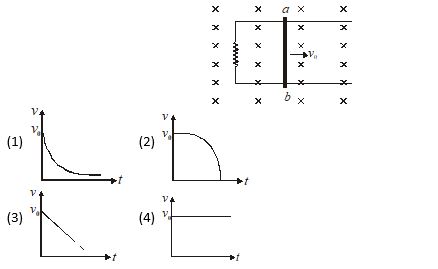
A conducting rod ab shown in figure moves on two frictionless parallel rails in a uniform magnetic field B. If rod is given an initial velocity (v0) at t = 0. Plot the graph between velocity of rod (v) with time (t)
Ans. (a)
Q.13
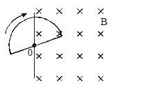
A semicircular loop of radius r is located on the boundary of a uniform magnetic field B. The loop is set into rotation with a constant angular acceleration about an axis coinciding with a line of vector \overrightarrow{{B\,}} on the boundary. Then emf induced (e) in the loop related with time (t) as
(a) e\propto {{t}^{0}}
(b) e\propto t
(c) e\propto {{t}^{2}}
(d) e\propto \frac{1}{t}
Ans. (b)
Q14
A conductor PQ, with \overrightarrow{{PQ}}=\overrightarrow{{r\,}}, moves with a velocity \overrightarrow{{v\,}} in a uniform magnetic field of induction \overrightarrow{{B\,}}. The emf induced in the rod is
(a) (\overrightarrow{{v\,}}\times \overrightarrow{{B\,}}).\,\overrightarrow{{r\,}}
(b) \overrightarrow{{v\,}}(\overrightarrow{{r\,}}\times \overrightarrow{{B\,}})
(c) \overrightarrow{{B\,.}}(\overrightarrow{{r\,}}\times \overrightarrow{{v\,}})
(d) |\overrightarrow{{r\,}}\times (\overrightarrow{{v\,}}\times \overrightarrow{{B\,}})|
Ans. (a)
Practice Questions (JEE Advance Level)
Q.1
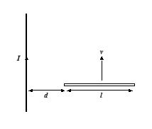
A long, straight wire has a constant current I. A metal rod of length l moves at velocity v relative to the wire, as shown in figure. What is the potential difference between the ends of the rod?
(a) \frac{{{{\mu }_{o}}I{{v}^{{}}}}}{{2\pi }}\,\ln \left| {\frac{{l\,+\,d}}{d}} \right|
(b) \frac{{{{\mu }_{o}}I{{v}^{2}}}}{{2\pi }}\,\ln \left| {\frac{{l\,+\,d}}{d}} \right|
(c) \frac{{{{\mu }_{o}}I{{v}^{2}}}}{{2\pi }}\,\ln \left| {\frac{{2l\,+\,d}}{{3d}}} \right|
(d) \frac{{{{\mu }_{o}}Iv}}{{2\pi }}\,\ln \left| {\frac{{2l\,+\,d}}{{3d}}} \right|
Ans : (a)
Q.2
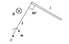
A conducting rod of length l attached to a rod of insulating material of length L is rotated with constant angular speed in a plane normal to the uniform magnetic field B, as shown in the figure. Then the emf produced across the ends of the conducting rod.
(a) E=\frac{1}{2}\omega B{{l}^{2}}\cos \omega t
(b) E=\frac{1}{2}\omega B{{l}^{2}}
(c) E=\frac{3}{2}\omega B{{l}^{2}}(\cos \omega t-1)
(d) E=\frac{1}{2}\omega B{{l}^{2}}\sin \omega t
Ans : (b)
Q.3
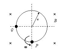
A conducting ring of radius a is rotated in a uniform magnetic field B about P in the plane of the paper as shown in the figure. If a resistance R is connected between P and Q ,then the current through the resistor must be
(a) I=\frac{{B\omega {{a}^{2}}}}{R}\cos \omega t
(b) I=\frac{{3B\omega {{a}^{2}}}}{{10R}}
(c) I=\frac{{B\omega {{a}^{2}}}}{{4R}}]
(d) I=\frac{{B\omega {{a}^{2}}}}{R}
Ans : (d)
Q.4
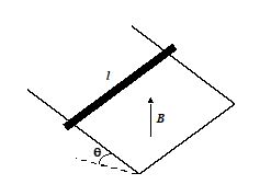
A conducting rod of mass m, length l and resistance R slides down a pair of frictionless rails of negligible resistance inclined at angle q to the horizontal. A uniform magnetic field is directed vertically upward. Then the terminal velocity attained by the rod must be
(a) v=\frac{{mgr\sin \theta }}{{{{{(Bl\cos \theta )}}^{2}}}}
(b) v=\frac{{2mgr\sin \theta }}{{Bl\cos \theta }}
(c) v=\frac{{mgr{{{\sin }}^{2}}\theta }}{{Bl\cos \theta }}
(d) v=\frac{{mgr\cos \theta }}{{{{{(Blsin\theta )}}^{2}}}}
Ans : (a)
Q.5
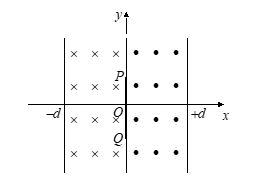
A straight conducting rod PQ is executing SHM in xy plane from x = –d to x = +d. Its mean position is x = 0 and its length is along y-axis. There exists a uniform magnetic field B from x = –d to x = 0 pointing inward normal to the paper and from x = 0 to x = +d there exists another uniform magnetic field of same magnitude B but pointing outward normal to the plane of the paper. At the instant t = 0, the rod is at
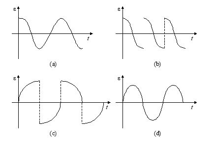
x = 0 and moving to the right. The induced emf (e) across the rod PQ vs time (t) graph will be
Ans. (b)
Comprehension ( Q.6 to Q.8)
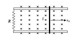
A metal rod of mass m and of length l slides on frictionless rails of negligible resistance, which terminate in a resistor R as shown in the figure. A uniform magnetic field B is directed perpendicular to the plane of the rails. If the initial velocity of the rod is vo and there is no external agent applying a force on the rod,
Q.6
Find the instantaneous velocity of the rod.
(a) \displaystyle v={{v}_{o}}{{e}^{{-t/\tau }}}
(b) \displaystyle v={{v}_{o}}{{e}^{{-2t/\tau }}}
(c) \displaystyle v={{v}_{o}}(1-{{e}^{{-t/\tau }}})
(d) \displaystyle v={{v}_{o}}(1+{{e}^{{-t/\tau }}})
Where \displaystyle \tau =\frac{{mR}}{{{{{(Bl)}}^{2}}}}
Ans : (a)
Q.7
Find the distance x travelled by the rod before it stops.
(a) \displaystyle x=\frac{{mR{{v}_{o}}}}{{Bl}}
(b) \displaystyle x=\frac{{mR{{v}_{o}}}}{{{{{(Bl)}}^{2}}}}
(c) \displaystyle x=\frac{{2mR{{v}_{o}}}}{{3{{{(Bl)}}^{2}}}}
(d) \displaystyle x=\sqrt{{\frac{{mR{{v}_{o}}}}{{{{{(Bl)}}^{2}}}}}}
Ans : (b)
Q.8
Find the total energy dissipated in the resistor.
(a) mv_{o}^{2}
(b) \frac{1}{4}mv_{o}^{2}-{{I}^{2}}R.\tau
(c) \frac{1}{2}mv_{o}^{2}+{{I}^{2}}R.\tau
(d) \frac{1}{2}mv_{o}^{2}
Ans : (d)
Q.9
A long straight wire carries a current Io. At distances a and b from it there are two other wires, parallel to the former one, which are interconnected by a resistance R (Fig.). A connector slides without friction along the wires with a constant velocity v. Assuming the resistances of the wires, the connector, the sliding contacts, and the self-inductance of the frame to negligible.The force required to maintain the connector’s velocity constant must be
(a) {{\left[ {\frac{{{{\mu }_{o}}I}}{\pi }\ln \left| {\frac{b}{a}} \right|} \right]}^{2}}\frac{v}{R}
(b) {{\left[ {\frac{{{{\mu }_{o}}I}}{{2\pi }}\ln \left| {\frac{b}{a}} \right|} \right]}^{2}}\frac{v}{R}
(c) {{\left[ {\frac{{3{{\mu }_{o}}I}}{{2\pi }}\ln \left| {\frac{b}{a}} \right|} \right]}^{2}}\frac{v}{R}
(d) {{\left[ {\frac{{{{\mu }_{o}}I}}{{2\pi }}\ln \left| {\frac{{2b}}{a}} \right|} \right]}^{2}}\frac{v}{R}
Ans : (b)

