Video Lecture
Theory For Making Notes
LCR Series Circuit
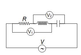
This is a general series a.c. circuit figure shows R, L and C connected in series across a supply voltage E (r.m.s.) The resulting current in the circuit is I (r.m.s.).
Voltage across R, \displaystyle {{V}_{R}}=IR …. where \displaystyle {{V}_{R}} is in phase with I
Voltage across L, \displaystyle {{V}_{L}}=I.{{X}_{L}} …. where \displaystyle {{V}_{L}} leads I by \displaystyle {{90}^{o}}
Voltage across C, \displaystyle {{V}_{C}}=I.{{X}_{C}} …. where \displaystyle {{V}_{C}} lags behind I by \displaystyle {{90}^{o}}
As before, the phasor diagram is drawn taking current as the reference phasor.
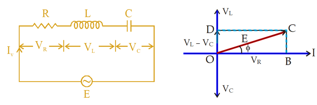
Therefore, the applied voltage E is the phasor sum of \displaystyle {{V}_{R}} and \displaystyle {{V}_{L}}-{{V}_{C}} and is represented by OC
\displaystyle E=\sqrt{{V_{R}^{2}+{{{({{V}_{L}}-{{V}_{C}})}}^{2}}}}
\displaystyle E=\sqrt{{{{IR}^{2}}+{{{({I{X}_{L}}-{I{X}_{C}})}}^{2}}}}
\displaystyle E= I\sqrt{{{{R}^{2}}+{{{({{X}_{L}}-{{X}_{C}})}}^{2}}}}
or \displaystyle I=\frac{E}{{\sqrt{{{{R}^{2}}+{{{({{X}_{L}}-{{X}_{C}})}}^{2}}}}}}
The quantity \displaystyle \sqrt{{{{R}^{2}}+{{{({{X}_{L}}-{{X}_{C}})}}^{2}}}} offers opposition to the current flow and is called impedance (Z) of the circuit. The phase difference between E and I can be found by finding tan f in DOBC
\displaystyle \tan \phi =\frac{{{{V}_{L}}-{{V}_{C}}}}{{{{V}_{R}}}}=\frac{{{{X}_{L}}-{{X}_{C}}}}{R} … (6)
Three cases of L-C-R series circuit
If the equation of the supply voltage is \displaystyle E\text{ }=\text{ }{{E}_{o}}~sin\omega t, then equation for the current will be
\displaystyle I\text{ }=\text{ }{{I}_{o}}sin\text{ }(\omega t\text{ }\pm \phi )\text{ }where\text{ }{{I}_{0}}~=\text{ }{{E}_{0}}~/\text{ }Z.
The value of \displaystyle \phi will be positive or negative depending upon which reactance(\displaystyle {{X}_{L}}~or\text{ }{{X}_{C}}) predominates.
We have seen above that impedance of a L-C-R series circuit is given by:
\displaystyle Z=\sqrt{{{{R}^{2}}+{{{({{X}_{L}}-{{X}_{C}})}}^{2}}}}
(i) When \displaystyle {{\text{X}}_{\text{L}}}\text{ }\!\!~\!\!\text{ – }{{\text{X}}_{{\text{C }\!\!~\!\!\text{ }}}} is positive
(i.e. \displaystyle {{X}_{L}} > \displaystyle {{X}_{C}} ),
phase angle \displaystyle \phi is positive and the circuit will be inductive. In other words, in such a case, the circuit current I will lag behind the supply voltage E by an angle \displaystyle \phi ; the value of \displaystyle \phi being given by equation (6) above
(ii)When \displaystyle {{\text{X}}_{\text{L}}}\text{ }\!\!~\!\!\text{ – }{{\text{X}}_{{\text{C }\!\!~\!\!\text{ }}}} is negative
(i.e. \displaystyle {{X}_{C}} > \displaystyle {{X}_{L}}),
phase angle \displaystyle \phi is negative and the circuit is capacitive. That is to say, the circuit current I leads the supply voltage E by \displaystyle \phi ; the value of \displaystyle \phi being given by equation (6) above
(iii)When \displaystyle {{\text{X}}_{\text{L}}}\text{ }\!\!~\!\!\text{ – }{{\text{X}}_{{\text{C }\!\!~\!\!\text{ }}}} is zero
(i.e. \displaystyle {{X}_{C}} = \displaystyle {{X}_{L}}),
the circuit is purely resistive. In other words, circuit current I and supply voltage E are in phase i.e. \displaystyle \phi = \displaystyle {{0}^{o}}.
Illustration 1
A 110V ac source of frequency 500 Hertz is connected to an LCR circuit with L = 8.1 mH, C = 12.5 \displaystyle \mu F and R = 10 \displaystyle \Omega all connected in series. Find the potential difference (PD) across the resistance.
Solution
As here,
\displaystyle {{X}_{L}}= \displaystyle \omega L=2\pi fL=2\times \pi \times 500\times 8.1\times {{10}^{{-3}}}
= 8.1 \displaystyle \pi = 25.431\displaystyle\Omega ,
\displaystyle {{X}_{C}}= \displaystyle \frac{1}{{\omega C}}=\frac{1}{{2\pi fC}}=\frac{1}{{2\pi \times 500\times 12.5\times {{{10}}^{{-6}}}}}=\frac{{{{{10}}^{3}}}}{{12.5\pi }}
= 25.478 \displaystyle \Omega ,
So,
\displaystyle X={{X}_{L}-{X}_{C}} = 25.431 – 25.478 = – 0.0437W
And hence \displaystyle Z=\sqrt{{{{R}^{2}}+{{X}^{2}}}}=\sqrt{{{{{(10)}}^{2}}+{{{(0.0437)}}^{2}}}}\simeq 10\Omega
So, I = \displaystyle \frac{V}{Z}=\frac{{100}}{{10}}=10A
and so VR = IR = 10 × 10 = 100V
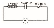
Illustration 2
An LCR circuit has L = 10 mH, R = 3 \displaystyle \Omega and C = 1 \displaystyle \mu F connected in series to a source of voltage E=15. cos \displaystyle (\omega t) V. Calculate the current amplitude and the average power dissipated per cycle at a frequency that is 10% lower than the resonance frequency.
Solution
As here,
\displaystyle {{\omega }_{0}}=\frac{1}{{\sqrt{{LC}}}}=\frac{1}{{\sqrt{{{{{10}}^{{-2}}}\times {{{10}}^{{-6}}}}}}}={{10}^{4}}\frac{{\text{rad}}}{\text{s}}
So,
\displaystyle \omega ={{\omega }_{0}}-\frac{{10}}{{100}}{{\omega }_{0}}=\frac{9}{{10}}{{\omega }_{0}}=9\times {{10}^{3}}\frac{{\text{rad}}}{\text{s}}
As, \displaystyle {{X}_{L}} = \displaystyle \omega L
So \displaystyle {{X}_{L}}= 9 × 103 × 10–2 = 90 \displaystyle \Omega
Also \displaystyle {{X}_{C}}=\frac{1}{{\omega C}}
hence \displaystyle {{X}_{C}}=\frac{1}{{9\times {{{10}}^{3}}\times {{{10}}^{{-6}}}}}=111.11\Omega
If net reactance is X , then
\displaystyle X={{X}_{L}} – \displaystyle {{X}_{C}}
= 90 – 111.11 = – 21.11 \displaystyle \Omega
and hence,
\displaystyle Z=\sqrt{{{{R}^{2}}+{{X}^{2}}}}=\sqrt{{{{3}^{2}}+{{{(-21.11)}}^{2}}}}
i.e. \displaystyle Z=\sqrt{{9+445.63}}=21.32\Omega
and as here
\displaystyle E=\text{ }15\text{ }cos\omega t, i.e. {{E}_{0}}=\text{ }15V,
\displaystyle {{I}_{0}}=\frac{{{{E}_{0}}}}{Z}=\frac{{15}}{{21.32}}=0.704A
The average power dissipated,
\displaystyle {{P}_{{\text{av}}}}={{V}_{{\text{rms}}}}{{I}_{{\text{rms}}}}\cos \phi =({{I}_{{\text{rms}}}}\times Z)\times {{I}_{{\text{rms}}}}\times \frac{R}{Z}
i.e. \displaystyle {{P}_{{\text{av}}}}=I_{{\text{rms}}}^{\text{2}}R=\frac{1}{2}I_{0}^{2}R \displaystyle \left[ {\text{as}\,\,{{I}_{{\text{rms}}}}=\frac{{{{I}_{0}}}}{{\sqrt{2}}}} \right]
So,
\displaystyle {{P}_{{\text{av}}}}=\frac{1}{2}\times {{(0.704)}^{2}}\times 3=0.74W
Now as \displaystyle f=\frac{\omega }{{2\pi }}=\frac{{9\times {{{10}}^{3}}}}{{2\pi }}\frac{{\text{cycle}}}{s}
So,
\displaystyle \frac{{{{P}_{{\text{av}}}}}}{{\text{cycle}}}=\frac{{0.74\,\,J/s}}{{(9\times {{{10}}^{3}}/2\pi )\,\,\,\text{cycle}/s}}
= \displaystyle\frac{{2\pi \times 0.74}}{{9\times {{{10}}^{3}}}}\frac{J}{{\text{cycle}}}
i.e. \displaystyle \frac{{{{P}_{{\text{av}}}}}}{{\text{cycle}}}=5.16\times {{10}^{{-4}}}\frac{J}{{\text{cycle}}}
Average power in L-C-R Circuit
In an a.c. circuit the instantaneous power is the product of the instantaneous value of the current and the voltage. Whereas the average power in any ac circuit can be found using relative
\displaystyle {{P}_{{av}}}=\frac{{\int\limits_{0}^{T}{{Pdt}}}}{{\int\limits_{0}^{T}{{dt}}}}=\frac{{\int\limits_{0}^{T}{{E\,.\,\,Idt}}}}{{\int\limits_{0}^{T}{{dt}}}}
where \displaystyle E={{\text{E}}_{o}}\text{sin}\omega t
\displaystyle I={{I}_{o}}\text{sin(}\omega t-\phi ) \displaystyle -{{90}^{0}}\le \phi \le {{90}^{0}}
Substituting the values of E and I in the above equation and solving we get
\displaystyle {{P}_{{av}}}=\frac{1}{2}{{E}_{0}}{{I}_{0}}\cos \phi ={{E}_{{rms}}}.{{I}_{{rms}}}.\cos \phi.
where \displaystyle {{E}_{{rms}}}.{{I}_{{rms}}} is called apparent power and \displaystyle cos\phi is known as power factor.
Power factor in an a.c. circuit is defined as the ratio of the actual power ( \displaystyle {{P}_{{av}}}) in watts (as measured by a watt meter) to the apparent power ( \displaystyle {{E}_{{rms}}}.{{I}_{{rms}}}) in volt-amperes (as indicated by the product of voltmeter and ammeter reading.
Power factor in L–C–R circuit is \displaystyle \cos \phi =\frac{{{{E}_{R}}}}{E}=\frac{{IR}}{{IZ}}, Hence
\displaystyle \cos \phi =\frac{R}{Z}=\frac{R}{{\sqrt{{{{R}^{2}}+{{{({{X}_{L}}-{{X}_{C}})}}^{2}}}}}}
If \displaystyle cos\phi = 0 or \displaystyle \phi =\frac{\pi }{2}
then \displaystyle {{P}_{{av}}} = 0
Under this condition, the current is known as wattless current, and it is given by \displaystyle I.sin\phi .
Note that on phasor diagram current I has two components, viz., \displaystyle I.cos\phi and \displaystyle I.sin\phi . The component \displaystyle I.cos\phi contributes to power and is called wattful component. However, component \displaystyle I.sin\phi does not contribute to any power and is rightly called wattles component.
Illustration 3
A series AC circuit contains an inductor (20 mH), a capacitor (100 \displaystyle \mu f), a resistor (50 \displaystyle \Omega ) and an AC source of 12V, 50Hz. Find the energy dissipated in the circuit in 1000s.
Solution
The time period of the source is
T = 1/F = 20 ms.
The given time 1000s is much larger than the time period.
Hence we can write the average power dissipated as
\displaystyle {{P}_{{av}}}~=\text{ }{{V}_{{rms}}}~{{I}_{{rms}}}~cos\phi where
\displaystyle cos\phi = R/Z is the power factor.
Thus,
\displaystyle {{P}_{{av}}}={{V}_{{rms}}}.\frac{{{{V}_{{rms}}}}}{Z}.\frac{R}{Z}=\frac{{R.V_{{rms}}^{2}}}{{^{{\mathop{Z}^{2}}}}}
= \displaystyle \frac{{(50)\,\,{{{(12)}}^{2}}}}{{{{Z}^{2}}}}
= \displaystyle \frac{{7200}}{{{{Z}^{2}}}}. … (1)
The capacitive reactance = \displaystyle \frac{1}{{\omega C}}=\frac{1}{{2\pi \times 50\times 100\times {{{10}}^{{-6}}}}}\Omega
= \displaystyle \frac{{100}}{\pi }\Omega .
The inductive reactance is \displaystyle \omega L , where
\displaystyle \omega L= \displaystyle 2\pi \times 50\times 20\times {{10}^{{-3}}}
hence \displaystyle \omega L= 2 \displaystyle \pi \displaystyle \Omega
If the net reactance is X,then
X = \displaystyle \frac{1}{{\omega C}}-\omega L
or X= \displaystyle \frac{{100}}{\pi }-2\pi \approx 25.5\Omega .
Thus,
\displaystyle {{Z}^{2}}~=\text{ }{{\left( {50} \right)}^{2}}~+\text{ }{{\left( {25.5} \right)}^{2}}~=\text{ }3150 .
From (1),
average power \displaystyle {{P}_{{av}}}=\frac{{7200}}{{3150}}=2.286W.
The energy dissipated in 1000s
= \displaystyle {{P}_{{av}}} × 1000s
= \displaystyle 2.286\text{ }\times \text{ }{{10}^{{3~}}}J.
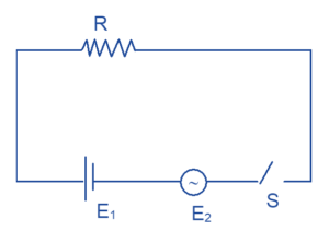
Illustration 4
In the circuit shown in figure R = 50 \displaystyle \Omega , E1 = 25 \displaystyle \sqrt{3} volt and E2 = 25 \displaystyle \sqrt{6} \displaystyle \text{sin}\omega t volt where \displaystyle \omega = 100 \displaystyle \pi \displaystyle {{s}^{{-1}}}. The switch s is closed at time t = 0 and is opened at t = 14 min. Find the amount of heat produced in the resistor.
Solution
I (t) = \displaystyle \frac{1}{R}({{E}_{1}}+{{E}_{2}})
= \displaystyle \frac{1}{{50}} (25 \displaystyle \sqrt{3} + 25 \displaystyle \sqrt{6} \displaystyle \text{sin}\omega t)
I (t) = \displaystyle \frac{{\sqrt{3}}}{2}(1+\sqrt{2}\sin \omega t)
Heat produced in one cycle of AC.
\displaystyle =\int\limits_{0}^{{2\pi /\omega }}{{{{I}^{2}}(t)Rdt}} ; putting the equation of I(t) and value of R we get
\displaystyle =\frac{3}{4}\times 50\int\limits_{0}^{{2\pi /\omega }}{{(1+{{{\sin }}^{2}}\omega t+2\sqrt{2}\sin \omega t)dt}}
= \displaystyle \frac{{75}}{2}\left[ {\frac{{2\pi }}{\omega }+\frac{{2\pi }}{\omega }} \right]=\frac{3}{2}J
No. of cycle in 14 minute is N = 14 x 60 x 50
Total heat produced = \displaystyle \frac{3}{2} x 14 x 60 x 50
Total heat produced = 3/2 x 14 x 60 x 50 = 63000 J
Alternative Method
Total heat produced will be sum of heat produced due to individual cell. Key in mind, heat is scalar, so we are going for this simplification
\displaystyle {{\left( {{{P}_{1}}} \right)}_{{avg.}}}= \displaystyle \frac{{({{E}_{1}})_{{\text{rms}}}^{2}}}{R}=37.5W
\displaystyle {{\left( {{{P}_{2}}} \right)}_{{avg.}}}.= \displaystyle \frac{{({{E}_{2}})_{{\text{rms}}}^{2}}}{R}
= \displaystyle \frac{{{{{(25\sqrt{6}/\sqrt{2})}}^{2}}}}{{12}}
= 37.5 W
Hence ,
Total heat produced = P1t + P2t
= (37.5 + 37.5) 14 × 60
= 63 × \displaystyle {{10}^{3}} J.
NOW TRY THESE SIMPLE QUESTIONS
1.
A coil has an inductance of 0.7 H and is joined in series with a resistance of 220 \displaystyle \Omega . When an alternating voltage of 220 V, 50 Hz is applied to it. Determine the power factor.
Ans. \displaystyle \frac{1}{{\sqrt{2}}}
[Hint: First find Z (Impedence) then apply formula of power factor \displaystyle \cos \phi =\frac{R}{Z}
2.
A circuit consisting of an inductance and a resistance is joined to a 200V a.c. supply. It draws a current of 10A. If the power used in the circuit is 1500W, find the power factor, the phase angle and the wattles current.
Ans. \displaystyle cos\phi =\frac{3}{4},\phi ={{\cos }^{{-1}}}\left( {\frac{3}{4}} \right),{{I}_{{wattless}}}=7.5A
Resonance in L-C-R Series AC circuit
The L-C-R series circuit is said to be in electrical resonance when
- \displaystyle {{X}_{L}}={{X}_{C}}
- \displaystyle Z=\sqrt{{{{R}^{2}}+{{{({{X}_{L}}-{{X}_{c}})}}^{2}}}}=R since \displaystyle {{X}_{L}}={{X}_{C}}, this is the minimum value of Z
- Since \displaystyle \cos \phi =\frac{R}{Z} hence the circuit power factor is unity, the maximum value of power factor
- Also because \displaystyle I=\frac{E}{Z} so I is maximum in resonace condition since Z is minimum
Since at series resonance the current flowing in the circuit is very large, the voltage drops across L and C are also very large. In fact, these drops are much greater than the applied voltage. However, voltage drop across L–C combination as a whole will be zero because VL & VC are out of phase with each other by \displaystyle \pi radians.
Effects of series resonance: When series resonance occurs, the effect on the circuit is the same as though neither inductance nor capacitance is present. The current under this condition is dependent solely on the resistance of the circuit and voltage across it.
The frequency at which resonance occurs is called the resonant frequency \displaystyle {{f}_{o}}.
At resonance,
\displaystyle {{X}_{L}} = \displaystyle {{X}_{C}}
or \displaystyle 2\pi {{f}_{0}}L=\frac{1}{{2\pi {{f}_{0}}C}}
or \displaystyle f_{0}^{2}=\frac{1}{{4{{\pi }^{2}}LC}}
or \displaystyle {{f}_{0}}=\frac{1}{{2\pi \sqrt{{LC}}}}
If L and C are in henry and farad respectively, then \displaystyle {{f}_{o}} will be in Hz.
Considering the resonance frequency again i.e.
\displaystyle {{f}_{0}}=\frac{1}{{2\pi \sqrt{{LC}}}}
\displaystyle \Rightarrow 2\pi .{{f}_{o}}=\frac{1}{{\sqrt{{LC}}}}
or \displaystyle {{\omega }_{o}}=\frac{1}{{\sqrt{{LC}}}}
here \displaystyle {{\omega }_{o}} is the resonant angular frequency
At series resonance as the impedance of the circuit is minimum and is equal to the resistance of the circuit i.e.
Z = R
The current in the circuit is maximum and is dependent only on the resistance of the circuit alone i.e.
\displaystyle I=\frac{E}{Z}=\frac{E}{R}
Resonance Curve
The curve between the circuit current and the supply frequency is known as resonance curve. Figure shows the resonance curve of a typical L-C-R series circuit. Note that current reaches the maximum value at the resonant angular frequency ( \displaystyle {{\omega }_{0}}), falling off rapidly on either side of that point.
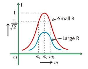
For values of \displaystyle \omega other than \displaystyle {{\omega }_{0}}, the amplitude of the current is less than the maximum values. Suppose we choose a value of w for which the current amplitude is \displaystyle 1/\sqrt{2} times its maximum value. From the curve in figure, we see that there are two such values of \displaystyle \omega which are \displaystyle {{\omega }_{1}} and \displaystyle {{\omega }_{2}}, one greater and the other smaller than \displaystyle {{\omega }_{0}} and symmetrical about \displaystyle {{\omega }_{0}}. We may write
\displaystyle {{\omega }_{1}}={{\omega }_{0}}+\Delta \omega
\displaystyle {{\omega }_{2}}={{\omega }_{0}}-\Delta \omega
The difference \displaystyle {{\omega }_{1}}-{{\omega }_{2}}=2\Delta \omega is often called the bandwidth of the circuit. The quantity ( \displaystyle {{\omega }_{0}}/2\Delta \omega ) is regarded as a measure of the sharpness of the curve. Greater the value of \displaystyle {{\omega }_{0}}/2\Delta \omega sharper or narrower is the resonance.
On solving we get
\displaystyle \Delta \omega =\frac{R}{{2L}}
The sharpness of resonance is given by,
\displaystyle \frac{{{{\omega }_{0}}}}{{2\Delta \omega }}=\frac{{{{\omega }_{0}}L}}{R}
Q-Factor of Series Resonant Circuit
At series resonance, the potential difference across L or C (The two voltage drops being equal and opposite) builds up to a value many times greater than the applied voltage E. The voltage magnification produced by series resonance is termed as Q-factor of the series resonant circuit (Q stands for quality) i.e.
The Q-factor of a resonant RLC circuit is the ratio of voltage across L (or C) to the applied voltage i.e.
Q-factor = \displaystyle \frac{{\text{voltage across L or C}}}{{\text{Applied voltage}}}
= \displaystyle \frac{{I.{{X}_{L}}}}{{I.R}}
= \displaystyle \frac{{{{X}_{L}}}}{R}
Q-factor = \displaystyle \frac{{{{X}_{L}}}}{R} \displaystyle =\frac{{{{\omega }_{0}}L}}{R} … (1)
Hence \displaystyle \frac{{{{w}_{0}}}}{{2\Delta {{w}_{0}}}}=Q,
The Q-factor of a series resonant circuit can also be expressed in terms of L and C.
We know that, \displaystyle {{\omega }_{0}}=\frac{1}{{\sqrt{{LC}}}} \displaystyle \left( {\because \,\,{{f}_{0}}=\frac{1}{{2\pi \sqrt{{LC}}}}} \right)
Substituting the value of \displaystyle {{\omega }_{0}} in equation \displaystyle Q=\frac{{{{w}_{0}}L}}{R} we get
Q-factor = \displaystyle \frac{1}{R}\sqrt{{\frac{L}{C}}}
The value of Q-factor depends entirely upon the design of the coil (i.e. R-L part of the R-L-C circuit) because resistance arises in this rather than in a capacitor.
Illustration 5
When a 15V dc source was applied across a choke coil then a current of 5 amp flows in it. If the same coil is connected to a 15V, 50 rad/s ac source a current of 3 amp flows in the circuit. Determine the inductance of the coil. Also find the power developed in the circuit and its resonance frequency if a 2500 \displaystyle \mu F capacitor is connected in series with the coil.
Solution
For a coil,
\displaystyle Z=\sqrt{{{{R}^{2}}+{{\omega }^{2}}{{L}^{2}}}}
\displaystyle I=\frac{V}{Z}=\frac{V}{{\sqrt{{{{R}^{2}}+{{\omega }^{2}}{{L}^{2}}}}}}
For dc source, \displaystyle\omega = 0
hence \displaystyle I=\frac{V}{R}
so R = \displaystyle \frac{{15}}{5}=3\Omega … (1)
When ac is applied
\displaystyle I=\frac{V}{Z} i.e. \displaystyle Z=\frac{{15}}{{3.0}}=5\Omega
or \displaystyle Z=\sqrt{{{{R}^{2}}+{{X}_{L}}^{2}}}=25
\displaystyle {{{X}_{L}}^{2}} = 25 – 9 = 16
or \displaystyle {{X}_{L}} = 4
hence \displaystyle \omega.L=4
or \displaystyle L=\frac{4}{{2\pi \times 50}}=0.0127 Henry.
Now when the capacitor is connected is series.
\displaystyle {{X}_{C}}=\frac{1}{{\omega C}}
= \displaystyle\frac{1}{{50\times 2500\times {{{10}}^{{-6}}}}}=8\Omega
\displaystyle Z=\sqrt{{{{R}^{2}}+{{{({{X}_{L}}-{{X}_{C}})}}^{2}}}}
So \displaystyle Z=\sqrt{{9+{{{(4-8)}}^{2}}}}=5\Omega
therefore \displaystyle I=\frac{{15}}{5}=3A
hence \displaystyle {{P}_{{av}}}={{V}_{{rms}}}.{{I}_{{rms}}}.cos\phi
= \displaystyle I_{{rms}}^{2} R = 9 × 3 = 27W.
Now \displaystyle {{f}_{o}} is the Resonance frequency
\displaystyle {{f}_{o}}=\frac{1}{{2\pi \sqrt{{LC}}}}
\displaystyle {{f}_{o}} = \displaystyle\frac{1}{{2\pi \sqrt{{(0.08)\times 2500\times {{{10}}^{{-6}}}}}}}
\displaystyle {{f}_{o}}=\frac{{1000}}{{2\pi \times 5\times 2\sqrt{2}}}
\displaystyle {{f}_{o}} =\frac{{25\sqrt{2}}}{\pi }=11.25\,\,Hz.
Practice Questions (Basic Level)
Q.1
An L–C–R series circuit is connected to a source of alternating current. At resonance the applied voltage and current flowing through the circuit will have a phase difference of
(a) zero (b) π / 4 (c) π / 2 (d) π
Ans. (a)
Q.2
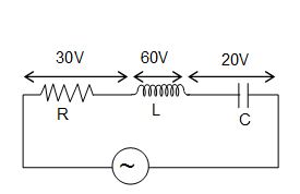
In a series L–C–R circuit the voltage across resistance, capacitance and inductance is 10 V each. If the capacitance is short circuited, the voltage across the inductance will be
(a) \displaystyle \frac{{10}}{{\sqrt{2}}}\,V
(b) 10 V
(c) \displaystyle 10\sqrt{2}\,V
(d) 20 V
Ans. (a)
Q.3
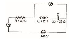
In the given figure, a series L–C–R circuit is connected to a variable frequency source of 230V. The impedance and amplitude of the current at the resonating frequency will be
(a) 20 Ω and 4.2 A
(b) 30 Ω and 6.9 A
(c) 25 Ω and 5.8 A
(d) 40 Ω and 5.75 A
Ans. (d)
Q.4
In the series L–C–R circuit shown, the impedance is
(a) 200 Ω
(b) 100 Ω
(c) 300 Ω
(d) 500 Ω
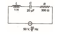
Ans. (d)
Q.5
The power factor of an R–L circuit is \displaystyle \frac{1}{{\sqrt{2}}}. If the frequency of AC is doubled, what will be the power factor ?
(a) \displaystyle \frac{1}{{\sqrt{3}}}
(b) \displaystyle \frac{1}{{\sqrt{5}}}
(c) \displaystyle \frac{1}{{\sqrt{7}}}
(d) \displaystyle \frac{1}{{\sqrt{{11}}}}
Ans. (b)
Q.6
In the circuit shown in figure neglecting source resistance, the voltmeter and ammeter readings will be respectively
(a) 0 V, 3 A (b) 150 V, 3 A (c) 150 V, 6 A (d) 0 V, 8 A
Ans. (d)
Q.7
The impedance of a circuit, when a resistance R and an inductor of inductance L are connected in series in an AC circuit of frequency f, is
(a) \displaystyle \sqrt{{R+2{{\pi }^{2}}{{f}^{2}}{{L}^{2}}}}
(b) \displaystyle \sqrt{{R+4{{\pi }^{2}}{{f}^{2}}{{L}^{2}}}}
(c) \displaystyle \sqrt{{{{R}^{2}}+4{{\pi }^{2}}{{f}^{2}}{{L}^{2}}}}
(d) \displaystyle \sqrt{{{{R}^{2}}+2{{\pi }^{2}}{{f}^{2}}{{L}^{2}}}}
Ans. (c)
Q.8
Voltage and current in an AC circuit are given by \displaystyle V=5\sin \left( {100\,\pi t-\frac{\pi }{6}} \right) and \displaystyle I=4\sin \left( {100\,\pi t+\frac{\pi }{6}} \right).
(a) voltage leads the current by 30º
(b) current leads the voltage by 30º
(c) current leads the voltage by 60º
(d) voltage leads the current by 60º
Ans. (c)
Q.9
An inductance of 1 mH, a condenser of 10 µF and a resistance of 50 Ω are connected in series. The reactances of inductor and condensers are same. The reactance of either of them will be
(a) 100 Ω (b) 30 Ω (c) 3.2 Ω (d) 10 Ω
Ans. (d)
Q.10
In L–C–R circuit, the capacitance is changed from C to 4C. For the same resonant frequency, the inductance should changed from L to
(a) 2 L (b) L / 2 (c) L / 4 (d) 4 L
Ans. (c)
Q.11
The resonant frequency of a circuit is f. If the capacitance is made 4 times the initial value, then the resonant frequency will become
(a) f / 2 (b) 2 f (c) f (d) f / 4
Ans. (a)
12.
In a series R-L-C circuit, R = 100 \displaystyle \Omega , XL = 300 \displaystyle \Omega and Xc = 200 \displaystyle \Omega . The phase angle \displaystyle \phi of the circuit is
(A) 00
(B) 900
(C) 450
(D) – 450
Ans (C)
13.
In a series LRC circuit, resonance occurs when
(A) R = XL ~ XC
(B) XL = XC
(C) XL = 10 XC more
(D) XL – XC> R
Ans (B)
14.
The power factor in AC circuit is equal to
(A) Z/R
(B) R/Z
(C) RZ
(D) none of the above
Ans (B)
15.
A series AC circuit has a resistance of 12 \displaystyle \Omega and reactance 5 \displaystyle \Omega . The impedance of circuit is
(A) 5 \displaystyle \Omega
(B) 12 \displaystyle \Omega
(C) 13 \displaystyle \Omega
(D) 17 \displaystyle \Omega
Ans (C)
16.
By what percentage the reactance in an AC circuit should be increased so that the power factor changes from (1/2) to (1/4)?
(a) 200%
(b) 100%
(c) 50%
(d) 400%
Ans (b)
17.
The angular frequency of a resonant LC combination (L = 10mH and C = 1 \displaystyle \mu F) is
(a) 1.0 × 10⁴ radian per sec
(b) 1.0 × 10⁴ Hz
(c) 1.0 × 10⁻⁴ radian per sec
(d) 1.0 × 10⁻⁴ Hz
Ans (a)
18.
An inductance coil of 1 Henry and a condenser of capacity 1pF produce resonance. The resonant frequency will be
(a) \frac{{{{{10}}^{6}}}}{{2\pi }}Hz
(b) \frac{{{{{10}}^{6}}}}{\pi }Hz
(c) \frac{{2\pi }}{{{{{10}}^{6}}}}Hz
(d) 2 \displaystyle \pi ´ 106 Hz
Ans (a)
Practice Questions (JEE Main Level)
Q.1
In a series LCR circuit, the frequencies f1 and f2 at which the current amplitude falls to \frac{1}{{\sqrt{2}}} of the current at resonance, are separated by an interval equal to (R/2pL).
(a) \displaystyle \frac{{2R}}{{\pi L}}
(b) \displaystyle \frac{R}{{2\pi L}}
(c) \displaystyle \frac{{7R}}{{2\pi L}}
(d) \displaystyle \frac{R}{L}
Ans : (b)
Q.2
A circuit element is placed in a black box. At t = 0, switch is closed and the current flowing through the circuit element and the voltage across its terminals are recorded to have the wave shapes shown in the figure. The type of element and its magnitude are
(a) inductance of 4 H
(b) resistance of 4 W
(c) capacitance of 1 F
(d) a voltage source of emf 4 V
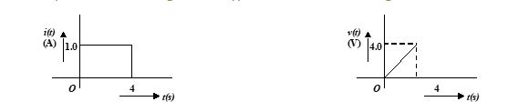
Ans. (c)
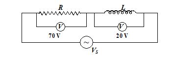
Q.3
The adjoining figure shows on A.C. circuit with resistance R, inductance L and source voltage Vs.
4.
In an a.c. circuit voltage v and current i are given by v = 100 sin 100 t volts,
i = 100 sin {100 t + \displaystyle \pi /3} mA. The power dissipated in the circuit is
(A) 104 W
(B) 10 W
(C) 2.5 W
(D) 5 W
Ans (D)
5.
In the a.c. circuit shown in the following figure, the resultant potential difference is
(A) 110 V
(B) 10 V
(C) 50 V
(D) 70 V
Ans (C)
6.
An alternating voltage E = E0 sin \displaystyle \omega t, is applied across a coil of inductor L. The current flowing through the circuit at any instant t is
(A) E0 / \displaystyle \omega L sin ( \displaystyle \omega t + \displaystyle \pi /2)
(B) E0 / \displaystyle \omega L sin ( \displaystyle \omega t – \displaystyle \pi /2)
(C) E0 \displaystyle \omega L sin ( \displaystyle \omega t – \displaystyle \pi /2)
(D) E0 \displaystyle \omega L sin ( \displaystyle \omega t + \displaystyle \pi /2)
Ans (B)
7.
In an R-L-C circuit v = 20 sin (314 t + 5 \displaystyle \pi /6) and i = 10 sin (314 t + 2 \displaystyle \pi /3) The power factor of the circuit is
(A) 0.5
(B) 0.966
(C) 0.866
(D) 1
Ans (C)
8.
The impedance of the circuit is
(A) \sqrt{{{{R}^{2}}+{{{\left( {\frac{{\omega L}}{{1-{{\omega }^{2}}LC}}} \right)}}^{2}}}}
(B) \sqrt{{\frac{1}{{{{R}^{2}}}}+{{{\left( {\frac{1}{{\omega L-1/\omega C}}} \right)}}^{2}}}}
(C) \sqrt{{{{R}^{2}}+{{{\left( {\omega L-\frac{1}{{1-\omega C}}} \right)}}^{2}}}}
(D) none of the above
Ans (A)
9.
In a series LCR circuit, the frequencies {{f}_{1}} and {{f}_{2}} at which the current amplitude falls to 1/\sqrt{2} of the current amplitude at resonance are separated by frequency interval
(a) \frac{R}{{2\pi L}}
(b) 2\pi \sqrt{{LC}}
(c) \sqrt{{LC}}
(d) RC
Ans (a)
10.
An alternating potential V={{V}_{0}}\sin \omega t is applied across a circuit. As a result, the current I={{I}_{0}}\sin \left( {\omega t-\frac{\pi }{2}} \right) flows in it. The power consumed in the circuit per cycle is
(a) zero
(b) 0.5 {{V}_{0}}{{I}_{0}}
(c) 0.707 {{V}_{0}}{{I}_{0}}
(d) 1.414 {{V}_{0}}{{I}_{0}}
Ans (a)
11.
What is the r.m.s. value of an alternating current which when passed through a resistor produce heat which is thrice that produced by a current of 2 ampere in the same resistor
(a)6.00A
(b) 2.00 A
(c)3.46A
(d) 0.65 A
Ans (c)
12.
An alternating voltage V = V0 sin \displaystyle \omega t is connected to a capacitor of capacity C0 through an AC ammeter of zero resistance. The reading of ammeter is
(a) \frac{{{{V}_{0}}\sqrt{2}}}{{\omega C}}
(b) \frac{{{{V}_{0}}}}{{\omega C\sqrt{2}}}
(c) \frac{{{{V}_{0}}\omega C}}{{\sqrt{2}}}
(d) none of these
Ans (c)
13.
Calculate the r.m.s. value of e.m.f. given by E=50\sqrt{2}\sin \left( {\omega t-\frac{\pi }{4}} \right)
(a) 50 V
(b) 5 V
(c) 2\sqrt{5}V
(d) None of these
Ans (a)
14.
An inductance coil of 1 Henry and a condenser of capacity 1pF produce resonance. The resonant frequency will be
(a) \frac{{{{{10}}^{6}}}}{{2\pi }}Hz
(b) \frac{{{{{10}}^{6}}}}{\pi }Hz
(c) \frac{{2\pi }}{{{{{10}}^{6}}}}Hz
(d) 2 \displaystyle \pi ´ 106 Hz
Ans (a)
15.
An alternating voltage V = V0 sin wt is applied across a circuit. As a result a current I = I0 sin ( \displaystyle \omega t – \displaystyle \pi /2) flows in it. The power consumed per cycle is
(a) zero
(b) 0.5 V0I0
(c) 0.707 V0I0
(d)1.414 V0I0
Ans (a)
16.
Using an AC voltmeter the potential difference in the electrical line in a house is read to be
234 volt. If the line frequency is known to be 50 cycles/second, the equation for the line voltage is
(a) V = 165 sin (100 pt)
(b) V = 331 sin (100 pt)
(c) V = 220 sin (100 pt)
(d) V = 440 sin (100 pt)
Ans (b)
Practice Questions (JEE Advance Level)
1.
In an L–R circuit, the inductive reactance is equal to the resistance R of the circuit. An emf
E = E0 cos ( \displaystyle \omega t) is applied to the circuit. The power consumed in the circuit is
(a) \frac{{E_{0}^{2}}}{{\sqrt{2}R}}
(b) \frac{{E_{0}^{2}}}{{4R}}
(c) \frac{{E_{0}^{2}}}{{2R}}
(d) \frac{{E_{0}^{2}}}{{8R}}
Ans (b)
2.
In the series LCR circuit, the voltmeter and ammeter readings are respectively
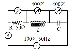
(a) V = 100 V, I = 2 A
(b) V = 1000 V, I = 5 A
(c) V = 1000 V, I = 2 A
(d) V = 300 V, I = 1 A
Ans (a)
3.
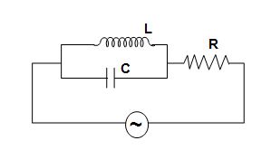
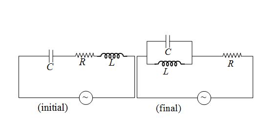
The current flowing through the resistor in a series L–C–R a.c. circuit, is I=\varepsilon /R.. Now the inductor and capacitor are connected in parallel and joined in series with the resistor as shown in figure. The current in the circuit is now. (Symbols have their usual meaning)
(a) equal to I
(b) more than I
(c) less than I
(d)zero
Ans (d)
4.
In a RLC series circuit shown, the readings of voltmeters and are 100 V and 120 V, respectively. If source voltage is 130 V
(a) Voltage across resistor is 50 V.
(b) Voltage across inductor is 86.6 V.
(c) Voltage across Capacitor is 206.6 V
(d) All of these
Ans (d)
5.
In the circuit shown in figure, the a.c. source gives a voltage V = 12cos(2000t). Neglecting source resistance, the current in the circuit will be

(a) 0 A
(b) 2 A
(c) 1.4 A
(d) 0.5 A
Ans (c)
6.
The power factor of wattless current is
(a) 0
(b) 1/2
(c) 1
(d) \displaystyle \infty
Ans (a)
7.
In the circuit shown in the figure, if both the bulbs B1 and B2 are identical, then
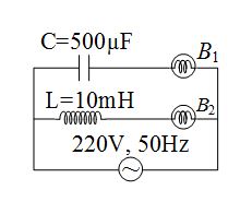
(a) their brightness will be the same
(b) as frequency of supply voltage is increased, brightness of B1 will decrease and that of B2 will increase
(c) as frequency of supply voltage is increased, brightness of B1 will increase and that of B2 will decrease
(d) only B2 will glow because the capacitor has infinite impedance.
Ans (c)
8.
A 750 Hz, 20 volt source is connected to a resistance of 100 ohm, an inductance of \frac{1}{{1000\pi }}H and a capacitance of \frac{1}{{2250\pi }}F, all in series. The time in which the temperature of the resistance increases by 10°C is (thermal capacity = 2 SI unit) (a) 2.5 sec
(b) 5 sec
(c) 7. 5sec
(d) 10 sec
Ans (b)
9.
A capacitor and resistor are connected with an A.C. source as shown in figure. Reactance of capacitor is XC= 3 \displaystyle \Omega and resistance of resistor is 4\Omega . Phase difference between current I and I1 is \left[ {{{{\tan }}^{{-1}}}\left( {\frac{4}{3}} \right)=53{}^\text{o}} \right]
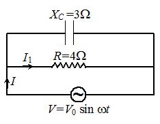
(a)900
(b)zero
(c)53º
(d) 37º
Ans (c)
10.
A circuit consists of a capacitor and a resistor having resistance R = 220 \displaystyle \Omega connected in series. When an alternating e.m.f. of peak voltage V0 = 220 \sqrt{2} V is applied to the circuit, the peak current in steady state is observed to be I0 = 1A. The phase difference between the current and the voltage is
(a) 30°
(b) 45°
(c) 60°
(d) 90°
Ans (b)
Comprehension ( Question No.- 11 to 14 )
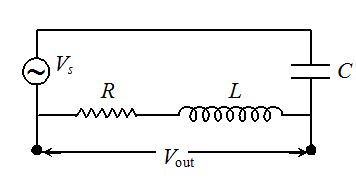
One application of LRC series circuits is to high pass or low pass filters, which filter out either the low or high frequency components of a signal. A high pass filter is shown in figure, where the output voltage is taken across the LR combination, where LR combination represents an inductance coil that also has resistance due to large length of the wire in the coil.
11.
The ratio of Vout/Vs as a function of the angular frequency \displaystyle \omega of the source is
(a) \sqrt{{\frac{{{{R}^{2}}+\omega {{L}^{2}}}}{{{{R}^{2}}+{{{\left( {\omega L-\frac{1}{{\omega C}}} \right)}}^{2}}}}}}
(b) \sqrt{{\frac{{{{R}^{2}}+{{{\left( {\omega L} \right)}}^{2}}}}{{{{R}^{2}}+{{{\left( {\omega L-\frac{1}{{\omega C}}} \right)}}^{2}}}}}}
(c) \sqrt{{\frac{{{{R}^{2}}+{{\omega }^{2}}L}}{{{{R}^{2}}+{{{\left( {\omega C-\frac{1}{{\omega L}}} \right)}}^{2}}}}}}
(d) 1
Ans (b)
12.
If \displaystyle \omega is negligibly small then the value of Vout /Vs is
(a) \displaystyle \omega RC
(b) \frac{{\omega R}}{L}
(c) \frac{{\omega R}}{L}RL
(d) \frac{{\omega R}}{C}
Ans (a)
13.
For large value of \frac{{\omega R}}{C}, the value of Vout/Vs is
(a) 1
(b) \frac{{\omega R}}{C}RC
(c) \frac{{\omega R}}{C}RL
(d) \frac{{\omega R}}{L}
Ans (a)
14.
The ratio of Vout/Vs at resonance is
(a) \sqrt{{\frac{{{{R}^{2}}+{{{\left( {\omega L} \right)}}^{2}}}}{{{{{\left( {\omega L} \right)}}^{2}}}}}}
(b) \sqrt{{\frac{{{{R}^{2}}+{{{\left( {\omega L} \right)}}^{2}}}}{{{{R}^{2}}}}}}
(c) \sqrt{{\frac{{{{R}^{2}}-\omega {{L}^{2}}}}{{{{R}^{2}}}}}}
(d) 1
Ans (b)
Comprehension ( Question No.- 15 to 17 )
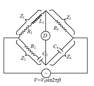
Figure shows a basic AC bridge. The four arms of the bridge have impedances Z1, Z2, Z3 and Z4. The condition for balance of bridge require that there should be no current through the detector D. Basic equation for balance of AC bridge is {{Z}_{1}}{{Z}_{4}}={{Z}_{2}}{{Z}_{3}}. If we work in terms of rectangular co-ordinates then \left( {{{R}_{1}}+j{{X}_{1}}} \right)\left( {{{R}_{4}}+j{{X}_{4}}} \right)=\left( {{{R}_{2}}+j{{X}_{2}}} \right)\left( {{{R}_{3}}+j{{X}_{3}}} \right). Impedance (Z) for resistance is R,for inductor is jwL and for capacitor is \frac{1}{{j\omega C}}=-\frac{j}{{\omega C}}. Equivalent impedance in series is given by Z={{Z}_{1}}+{{Z}_{2}}+ ………….. and in parallel it is given by \frac{1}{Z}=\frac{1}{{{{Z}_{1}}}}+\frac{1}{{{{Z}_{2}}}}+……..
A complex equation is satisfied only if real and imaginary parts of each side of the equation are separately equal. Thus there are two independent conditions for both of them that must be satisfied for the bridge to be balanced.
15.
Value of Z2 is
(a) {{R}_{2}}+\frac{j}{{\omega {{C}_{2}}}}
(b) {{R}_{2}}+j\omega {{C}_{2}}
(c) {{R}_{2}}+\frac{1}{{j\omega {{C}_{2}}}}
(d) {{R}_{2}}+\frac{{{{C}_{2}}}}{{j\omega }}
Ans (c)
16.
Balance condition for real term is
(a) {{R}_{2}}{{R}_{3}}={{C}_{4}}{{L}_{1}}
(b) {{L}_{1}}={{R}_{2}}{{R}_{3}}{{C}_{4}}
(c) {{L}_{1}}{{C}_{2}}={{R}_{2}}{{R}_{3}}
(d) {{L}_{1}}{{R}_{2}}={{R}_{3}}{{C}_{4}}
Ans (b)
17.
If {{L}_{1}}={{R}_{2}}{{R}_{3}}\,\,{{C}_{4}} and there is no current in detector then \frac{{{{R}_{1}}}}{{{{R}_{3}}}} is
(a) \frac{{{{C}_{4}}}}{{{{C}_{2}}}}
(b) \frac{{{{C}_{2}}}}{{{{C}_{4}}}}
(c) {{C}_{4}}{{C}_{2}}
(d) \frac{1}{{{{C}_{2}}{{C}_{4}}}}
Ans (a)