Video Lecture
Theory For Notes Making
Lorem ipsum dolor sit amet, consectetur adipiscing elit. Ut elit tellus, luctus nec ullamcorper mattis, pulvinar dapibus leo.
Objective Assignment
Q.1
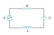
An L–C–R series circuit is connected to a source of alternating current. At resonance the applied voltage and current flowing through the circuit will have a phase difference of
(a) zero (b) π / 4 (c) π / 2 (d) π
Ans. (a)
Q.2
In a series L–C–R circuit the voltage across resistance, capacitance and inductance is 10 V each. If the capacitance is short circuited, the voltage across the inductance will be
(a) \displaystyle \frac{{10}}{{\sqrt{2}}}\,V
(b) 10 V
(c) \displaystyle 10\sqrt{2}\,V
(d) 20 V
Ans. (a)
Q.3
In the given figure, a series L–C–R circuit is connected to a variable frequency source of 230V. The impedance and amplitude of the current at the resonating frequency will be
(a) 20 Ω and 4.2 A
(b) 30 Ω and 6.9 A
(c) 25 Ω and 5.8 A
(d) 40 Ω and 5.75 A
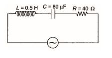
Ans. (d)
Q.4
In the series L–C–R circuit shown, the impedance is
(a) 200 Ω
(b) 100 Ω
(c) 300 Ω
(d) 500 Ω
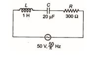
Ans. (d)
Q.5
The power factor of an R–L circuit is \displaystyle \frac{1}{{\sqrt{2}}}. If the frequency of AC is doubled, what will be the power factor ?
(a) \displaystyle \frac{1}{{\sqrt{3}}}
(b) \displaystyle \frac{1}{{\sqrt{5}}}
(c) \displaystyle \frac{1}{{\sqrt{7}}}
(d) \displaystyle \frac{1}{{\sqrt{{11}}}}
Ans. (b)
Q.6
In the circuit shown in figure neglecting source resistance, the voltmeter and ammeter readings will be respectively
(a) 0 V, 3 A (b) 150 V, 3 A (c) 150 V, 6 A (d) 0 V, 8 A
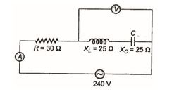
Ans. (d)
Q.7
The impedance of a circuit, when a resistance R and an inductor of inductance L are connected in series in an AC circuit of frequency f, is
(a) \displaystyle \sqrt{{R+2{{\pi }^{2}}{{f}^{2}}{{L}^{2}}}}
(b) \displaystyle \sqrt{{R+4{{\pi }^{2}}{{f}^{2}}{{L}^{2}}}}
(c) \displaystyle \sqrt{{{{R}^{2}}+4{{\pi }^{2}}{{f}^{2}}{{L}^{2}}}}
(d) \displaystyle \sqrt{{{{R}^{2}}+2{{\pi }^{2}}{{f}^{2}}{{L}^{2}}}}
Ans. (c)
Q.8
Voltage and current in an AC circuit are given by \displaystyle V=5\sin \left( {100\,\pi t-\frac{\pi }{6}} \right) and \displaystyle I=4\sin \left( {100\,\pi t+\frac{\pi }{6}} \right).
(a) voltage leads the current by 30º
(b) current leads the voltage by 30º
(c) current leads the voltage by 60º
(d) voltage leads the current by 60º
Ans. (c)
Q.9
An inductance of 1 mH, a condenser of 10 µF and a resistance of 50 Ω are connected in series. The reactances of inductor and condensers are same. The reactance of either of them will be
(a) 100 Ω (b) 30 Ω (c) 3.2 Ω (d) 10 Ω
Ans. (d)
Q.10
In L–C–R circuit, the capacitance is changed from C to 4C. For the same resonant frequency, the inductance should changed from L to
(a) 2 L (b) L / 2 (c) L / 4 (d) 4 L
Ans. (c)
Q.11
The resonant frequency of a circuit is f. If the capacitance is made 4 times the initial value, then the resonant frequency will become
(a) f / 2 (b) 2 f (c) f (d) f / 4
Ans. (a)
12.
In a series R-L-C circuit, R = 100 \displaystyle \Omega , XL = 300 \displaystyle \Omega and Xc = 200 \displaystyle \Omega . The phase angle \displaystyle \phi of the circuit is
(A) 00
(B) 900
(C) 450
(D) – 450
Ans (C)
13.
In a series LRC circuit, resonance occurs when
(A) R = XL ~ XC
(B) XL = XC
(C) XL = 10 XC more
(D) XL – XC> R
Ans (B)
14.
The power factor in AC circuit is equal to
(A) Z/R
(B) R/Z
(C) RZ
(D) none of the above
Ans (B)
15.
A series AC circuit has a resistance of 12 \displaystyle \Omega and reactance 5 \displaystyle \Omega . The impedance of circuit is
(A) 5 \displaystyle \Omega
(B) 12 \displaystyle \Omega
(C) 13 \displaystyle \Omega
(D) 17 \displaystyle \Omega
Ans (C)
16.
By what percentage the reactance in an AC circuit should be increased so that the power factor changes from (1/2) to (1/4)?
(a) 200%
(b) 100%
(c) 50%
(d) 400%
Ans (b)
17.
The angular frequency of a resonant LC combination (L = 10mH and C = 1 \displaystyle \mu F) is
(a) 1.0 × 10⁴ radian per sec
(b) 1.0 × 10⁴ Hz
(c) 1.0 × 10⁻⁴ radian per sec
(d) 1.0 × 10⁻⁴ Hz
Ans (a)
18.
An inductance coil of 1 Henry and a condenser of capacity 1pF produce resonance. The resonant frequency will be
(a) \frac{{{{{10}}^{6}}}}{{2\pi }}Hz
(b) \frac{{{{{10}}^{6}}}}{\pi }Hz
(c) \frac{{2\pi }}{{{{{10}}^{6}}}}Hz
(d) 2 \displaystyle \pi ´ 106 Hz
Ans (a)
Subjective Assignment
Q.1
A series LCR circuit is connected to a 220 V variable frequency (a.c.) supply. If L = 10 mH, \displaystyle C=\,\left( {\frac{{400}}{{{{\pi }^{2}}}}} \right)\,\mu F and R = 55 \displaystyle \Omega .
(a) Find the frequency of the source, for which the average power absorbed by the circuit is maximum.
(b) Calculate the value of maximum current amplitude.
Q.2
Obtain the resonant frequency and Q-factor of a series LCR circuit with L = 3.0 H,C = 27 μF, and R = 7.4 Ω. It is desired to improve the sharpness of the resonance of the circuit by reducing its ‘full width at half maximum’ by a factor of 2. Suggest a suitable way.
Ans . \displaystyle {{\omega }_{0}}\,=\,111\,rad\,{{s}^{{-1}}};\,Q\,=\,45, To double Q without changing \displaystyle {{\omega }_{0}}, reduce R to 3.7 \displaystyle \Omega
Q.3
Define quality factor in electrical resonance circuit. Find quality factor of series resonance circuit.
Q.4
(a) Derive an expression for the average power consumed in a series LCR circuit connected to a.c. source in which the phase difference between the voltage and the current in the circuit is .
Q.5
A series LCR circuit is connected to an ac source having voltage \displaystyle v\,=\,{{v}_{m}} sin . Derive the expression for the instantaneous current I and its phase relationship to the applied voltage. Obtain the condition for resonance to occur. Define ‘power factor’. State the conditions under which it is (i) maximum and (ii) minimum.
Q.6
Derive an expression for the impedance of a series LCR circuit connected to an AC supply of variable frequency. Plot a graph showing variation of current with the frequency of the applied voltage. Explain briefly how the phenomenon of resonance in the circuit can be used in the tuning mechanism of a radio or a TV set.
Q.7
Figure shows a series LCR circuit connected to a variable frequency 230 V source. L = 5.0 H, C = 80μF, R = 40 Ω.
(a) Determine the source frequency which drives the circuit in resonance.
Ans. 50 rad \displaystyle {{s}^{{-1}}}
(b) Obtain the impedance of the circuit and the amplitude of current at the resonating frequency.
Ans. 40 \displaystyle \Omega 8.1 A
(c) Determine the rms potential drops across the three elements of the circuit. Show that the potential drop across the LC combination is zero at the resonating frequency.
Ans. \displaystyle {{V}_{{LCrms}}}\,=\,1437.5V,\,\,{{V}_{{Crms}}}\,=\,1437.5\,V,\,\,{{V}_{{Rms}}}\,=\,230V
Q.8
The inductance of a resistance coil is 0.5 henry. How much potential difference will be developed across it on passing an alternating current of 0.2 amp. if the frequency of current be 50 hertz? What will be the phase difference between the potential difference and current in the coil?
Ans. 31.4 volt, voltage leads current by 90°
Q.9
A coil of resistance 300 ohm an inductance 1H is connected across an alternating voltage of frequency 300/2p hertz. Calculate the phase diff. Between voltage and current in the circuit.
Ans. 45°
Q.10
A coil takes a current of 2.0 ampere and 200 watt power from an alternating current source of 220 volt, 50 hertz. Calculate resistance and inductance of the coil.
Ans. 50 W, 0.312 H
Q.11
An electric lamp marked 100 V d.c. consumes a current of 10 A. It is connected to a 200 V, 50 Hz a.c. mains. Calculate the inductance of the choke required.
Ans. 5.5´10-2 H
Q.12
When a series combination of inductance an resistance are connected with a 10 V, 50 Hz a.c. voltage leads the current of 1 A flows in the circuit. The voltage leads the current by a phase angle of p/3 radian. Calculate the values of resistance and inductance.
Ans. 5W, 27.57 mH
Q.13
When an electric device X is connected to a 220 volt, 50 hertz a.c supply, the current is 0.5 amp, and is in same phase as the applied voltage. When another device Y is connected to the same supply, the electric current is again 0.5 am, but it leads the potential difference by p/2. (i) What are the devices X and Y? (ii) When X and Y are connected in series across the same source, what will be the current?
Ans. X is resistor, Y is capacitor, 0.353 A
Q.14
find the capacity of a condenser to run a 30 volt, 10 watt lamp when connected in series with an alternating e.m.f of 220 volt and frequency 50 c/s.
Ans. 4.86 mF
Q.15
A circuit consists of a 2mF capacitor and a resistor of 1 kW. An a.c source of 12 V, 50 hz is connected across the circuit. Calculate (i) current flowing (ii) voltage across capacitor (iii) phase angle between voltage and current (iv) average power supplied.
Ans. 6.4´10-3 A, 10.2 V, 58°, 0.041 W
Q.16
A variable frequency 230 V alternating voltage source is connected across a series combination of L=5.0 H, C=80 mF an R=40 W. Calculate
(i) the angular frequency of the source which drives the circuit in resonance.
Ans. 50 rad/sec
(ii) amplitude of current at resonance frequency
Ans. 8.13 A
(iii) r.m.s potential drop across the inductor at resonating frequency.
Ans. 1437.5 V
Q.17
A 100 mH inductor, a 25 mF capacitor and a 15 ohm resistor are connected in series to a 120 V, 50 hz a.c. source. Calculate (i) impedance of the circuit at resonance, (ii) current at resonance (iii) Resonant frequency.
Ans. 15 W, 8A, 100.7 hz
Q.18
A 25.0 mF capacitor, a 0.10 henry inductor and a 25.o ohm resistor are connected in series with an a.c. source whose e.m.f is given by E=310 sin 314 t. (i) what is the frequency of the e.m.f? (ii) calculate (a) the reactance of the circuit (b) the impedance of the circuit, and (c) current in the circuit.
Ans. (i) 50 Hz (ii) (a) 95.84 W (b) 99.1 W (c) 2.21 A
Q.19
A inductor of inductance 100 mH is connected in series with a resistance, a variable capacitance and an ac source of frequency 2.0 kHz. What should be the value of the capacitance so that maximum current may be drawn into the circuit?
Ans. 63 nF
Q.20
A capacitor, a resistor and a 40 mH inductor are connected in series to an a.c. source of frequency 60 Hz. Calculate the capacitance of the capacitor, if current is in phase with the voltage.
Ans. 175.7 mF
Q.21
A coil of self inductance 0.16 H is connected to a condenser of capacity 0.81 mF. What should be the frequency of a.c. that should be applied so that there is resonance in the circuit. Resistance of circuit is negligible.
Ans. 441.9 hertz
Q.22
A coil of inductance 150 mH is connected in series with a variable capacitor of capacitance 20 pF to 500 pF. Calculate the frequency range to which the circuit can be tuned.
Ans. 1.84´104 Hz to 9.2´104 Hz
Q.23
A wave of length 300 m can be transmitted by a transmission centre. A condenser of capacity 2.4 mF is available. Calculate the inductance of the required coil for resonance.
Ans. 1.056´10-8 henry
Q.24
Obtain the resonant frequency (wr) of a series LCR circuit with L=2.0 H, C=32 mF and R=10 ohm. What is the Q value of this circuit?
Ans. 125 rad/s, 25
Q.25
A capacitor of 50 mF, a resistor of 10 ohm and \an inductor L are in series with an a.c. source of frequency 50 Hz. Calculate the value of L if phase angle between current and voltage is zero.
Ans. 0.2 H
Q.26
An a.c circuit containing 800 mH inductor and a 60 mF capacitor is in series with 15-ohm resistance. They are connected to 230 V, 50 Hz a.c supply. Obatain average power transferred to each element and total power absorbed.
Ans.PL=0,PC=0,PR=20.05watt,P=20.05 watt
Q.27
A 100 W electric iron is connected to 200 V, 50 Hz, a.c. source. Calculate average power delivered to iron, peak power and energy spent in one minute.
Ans. 400 W, 800 W, 12´105 J
Q.28
A group of electric bulbs have a power rating of 300 watt. An a.c. voltage V=141.4 sin (314t+p/3) is applied to the group. Calculate the effective current.
Ans. 3 A
Q.29
An a.c. voltage E=200 sin 300 t is applied across a series combination of R=10 W, and L=800 mH. Calculate the power factor of the circuit.
Ans. 0.0416
Q.30
Calculate the value of an inductance, which should be connected in series with a capacitance of 5mF and a resistance of 10 ohm and a.c. source of 50 hz, so that the power factor of the circuit is unity.
Ans. 2.028 H
Q.31
An LR circuit having L=4.0 H, R=1.0 W and E=6.0 v is switched on at t=0, Find the power dissipated in joule heating at t=4.0 s.
Ans. 14.4 watt
Q.32
At what frequencies would a 0.1 H inductor and a 10 mF capacitor have reactances of 500 W?
Ans. 796 Hz, 31.8 Hz
Q.33
Two different coils have self-inductances L1=8 mH and L2=2 mH. At a certain instant, the current in the two coils is increasing at the same constant rate and the power supplied to the two coils is the same. Find the ratio of (a) induced voltage (b) current and (c) energy stored in the two coils at that instant?
Ans. 4:1, 1:4, 1:4
Q.34
An LCR circuit has L=10 mH, R=3 W and C=1mF connected in series to a source of 15 cos wt. volt. Calculate the current amplitude and the average power dissipated per cycle at a frequency 10% lower than the resonance frequency.
Ans. 0.70 A, 0.736 W
Q.35
The dielectric strength of air is 3.0´106 V/m. a parallel-plate air capacitor has area 20 cm2 and plate separation 1.0 mm. Find the maximum r.m.s. voltage of an ac source which can be safely connected to this capacitor?
Ans. 212.2 V
Q.36
A coil has an inductance 0.7 H and is joined in series with a resistance of 220 ohm. Find the wattles component of current in the circuit, when an alternating emf of 220 V at a frequency of 50 hz is supplied to it.
Ans. 0.5 A
Q.37
The graphs, shown here, depict the variation of current \displaystyle {{i}_{m}} vs angular frequency ( \displaystyle \omega ) for two different series LCR circuits.
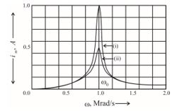
Observe the graphs carefully.
(a) State the relation between the L and C value of the two circuits, when the current in the two circuits is maximum.
(b) Indicate the circuit for which (a) power factor is higher. (b) quality factor (Q) is larger. Give reasons for each case.
Q.38
A circuit containing a 80 mH inductor and a 60 μF capacitor in series is connected to a 230V,50 Hz supply. The resistance of the circuit is negligible.
(a) Obtain the current amplitude and rms values.
Ans : For \displaystyle {{I}_{{rms}}}\,=\,5.75A, \displaystyle {{I}_{0}}\,=\,11.6\,A,\,\,{{I}_{{rms}}}=8.24\,A
(b) Obtain the rms values of potential drops across each element.
Ans.. \displaystyle {{I}_{{Lms}}}\,=\,207V,\,\,{{V}_{{Crms}}}=\,437\,V
(c) What is the average power transferred to the inductor?
Ans. Average power consumed by L is zero
(d) What is the average power transferred to the capacitor?
Ans. Average power consumed by C is zero
(e) What is the total average power absorbed by the circuit? [‘Average’ implies‘averaged over one cycle’.]
Ans. Total average power absorbed, is zero
Q.39
A series LCR circuit with L = 0.12 H, C = 480 nF, R = 23 Ω is connected to a 230 V variable frequency supply.
(a) What is the source frequency for which current amplitude is maximum. Obtain this maximum value.
(b) What is the source frequency for which average power absorbed by the circuit is maximum. Obtain the value of this maximum power.
(c) For which frequencies of the source is the power transferred to the circuit half the power at resonant frequency? What is the current amplitude at these
frequencies?
(d) What is the Q-factor of the given circuit?