Video Lecture
Theory For Making Notes
Nature of Light
Light is a form of energy which causes the sensation of sight in eyes, or it is a radiation of wavelength lying between ultraviolet and infrared radiation.
In ancient times a number of theories were proposed by different scientist, but no single theory could explain the nature and phenomena of light. Some of the famous theories about the nature of light are given below.
Newton’s Corpuscular theory
Newton considered light as a stream of weightless particles called corpuscles traveling with very high speed. He assumed that different colors of light are due to the different sizes of the corpuscles.
He explained that the reflection of light takes place because of force of repulsion between the corpuscles and the reflecting surface. Whereas he explained the refraction of light as when corpuscles fall on an interface separating rarer and denser medium, then the corpuscles are attracted by the denser medium. Hence, the light bends towards the normal and its speed decreases because of force of attraction.
Newton’s theory was quite conflicting because he assumed the force of repulsion between the corpuscles at the interface to explain the reflection of light and at the same time, he assumed the force of attraction between the corpuscles in the medium forming an interface to explain the refraction of light.
Huygens and Fresnel’s ether wave theory
In 1678, Huygen proposed his theory of wave nature of light in which he assumed that light is a periodic disturbance transmitted through an imaginary medium called aluminiferous ether or simply ether. But later on existence of ether could not be proved and hence the theory was rejected.
Wave theory of light given by Huygen explained the reflection and refraction of light successfully. This theory could not explain the rectilinear propagation of light.
Maxwell’s electromagnetic wave theory
According to this theory, light is an electromagnetic wave consisting of mutually perpendicular time varying electric and magnetic fields which are also perpendicular to the direction of the propagation of light wave. According to this theory, electromagnetic waves need no material medium for their propagation.
Since, this theory could not explain certain physical phenomenon like Photoelectric effect and Compton Effect, hence electromagnetic theory was not considered as the final theory of the nature of light. It failed completely to explain emission and absorption of radiation.
Quantum theory
Einstein put forwarded a new theory of the nature of light known as Quantum theory. He used Planck’s quantum hypothesis of black body radiations.
According to this theory, light consists of packets of energy known as photons. A photon is a massless particle which moves with speed of light. Each photon has energy equal to \displaystyle h\nu , where h = \displaystyle 6.63\times{{10}^{{34}}} J s is the Planck’s constant and \displaystyle \nu is the frequency of radiation. With the help of this theory, photo electric effect and Compton Effect were explained by Einstein and Compton respectively. This theory failed to explain interference, diffraction and polarization.
de-Broglie dual Nature of light
When scientist could not a frame a single theory to explain all the phenomenon of light, ultimately de-Broglie concluded that like matter, light has dual nature. His conclusion was based on the fact that, if radiation can behave like a particle (photon), then material particles can also behave like radiation. According to de Broglie, a moving material particle is always associated with a wave known as matter wave or de-Broglie wave.
Wavefront and Types of Wave fronts
Wavefront is defined as the locus of all the particles of a medium vibrating in the same phase at a given instant. The phase difference between any two points situated on the same wave front is zero. The shape of a wavefront depends upon the shape of the source of disturbance. There are different types of wave fronts which are given below
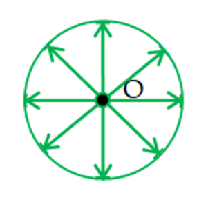
Spherical Wavefront
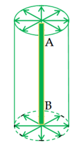
Cylindrical Wavefront

Plane Wavefront
Spherical wavefront
If the source of disturbance is a point source (O), then the wavefront is spherical. The intensity I of a spherical wavefront is inversely proportional to the square of the distance `r’ from the source. Hence \displaystyle I\propto \frac{1}{{{{r}^{2}}}}
Cylindrical wavefront
If the source of disturbance is a slit AB (i.e. line source) then the wavefront is cylindrical because all the points equidistant from the source lie on the surface of the cylinder. The intensity I of a cylindrical wavefront is inversely proportional to the distance `r’ from the source. Hence \displaystyle I\propto \frac{1}{r}
Plane wavefront
At a very large distance from the point source, a small part of the spherical wavefront appears plane and this part of the spherical wavefront is called plane wavefront. Thus, a spherical wavefront appears as plane wavefront after traveling a large distance from the point source. The intensity I of a plane wavefront remains same and does not change with distance.
Huygen’s Principle
Huygen’s principle gives geometrical details of traveling of a wave. This principle is used to find the position of the given wavefront at any instant if its present position in known.
According to Huygen’s principle : Each source of light is a centre of disturbance from which waves spread in all directions. All particles equidistant from the source and vibrating in same phase lie on a surface known as wavefront.
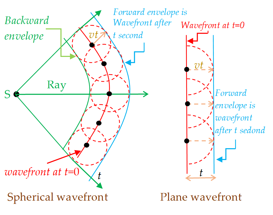
Every point on a wavefront is a source of new disturbance which produces secondary wavelets. These wavelets are spherical and travel with the speed of light in all directions in that medium. Only forward envelope enclosing the tangents of the secondary wavelets at any instant gives the new position of wavefront.
Limitation : Wavefront which shows backward propagation of light is not considered because only forward envelope is considered as per Huygen’s principles.
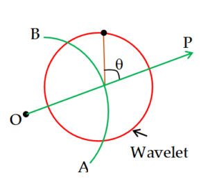
The amplitude and hence intensity due to the secondary wavelets depends on the obliquity factor i.e. ( \displaystyle 1+cos\theta ).
\displaystyle \theta = angle of point at which intensity is required w.r.t. direction of propagation
AB = wave front
OP = ray
Law Of Reflection from Huygen’s Theory
For the law of reflection, refer to Figure given below.
Consider light rays 1 and 2 moving towards a reflecting surface like a mirror as shown in the figure, It can be seen easily that out of the two rays the ray 1 will strike the surface first. We focus our attention on the instant ray 1 strikes the surface and the subsequent time interval \displaystyle \Delta t until ray 2 strikes the surface.
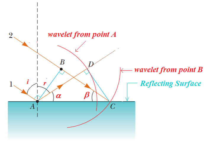
Just at the instant the ray 1 strikes the surface, the line AB represents a plane wave front of the incident light. At this instant, the wave at A sends out a Huygens wavelet (the red circular arc centered on A). The reflected light ray is AD and it propagates toward D. At the same time, the source at B emits a Huygens wavelet (the red circular arc centered on B) which is still propagating toward C and it takes \displaystyle \Delta t time to reach at C. By the time the wavelet from B reaches C the wavelet from A reaches D. Since the speed of both the wavelets is same i.e. `c’ therefore distance AD = BC = \displaystyle c\times \Delta t . The remaining analysis depends on geometry. Notice that the two triangles ABC and ADC are congruent because they have the same hypotenuse AC and because AD = BC. Figure shows that
From \displaystyle \Delta ABC \displaystyle \cos \beta =\frac{{BC}}{{AC}} and
from \displaystyle \Delta ADC \displaystyle \cos \alpha =\frac{{AD}}{{AC}}
Since \displaystyle AD=BC=c\times \Delta t therefore \displaystyle \cos \beta =\cos \alpha
hence \displaystyle \beta =\alpha
but \displaystyle \beta =90-i\text{ and }\alpha =90-r from the figure
therefore \displaystyle 90-i\text{ = }90-r
hence \displaystyle i = r (which is the law of reflection).
Law Of Refraction from Huygen’s Theory
Now let’s use Huygens’s principle and derive Snell’s law of refraction. Consider light rays 1 and 2 moving towards a refracting surface which is separating two mediums as shown in the figure, We focus our attention on the instant ray 1 strikes the surface and the subsequent time interval \displaystyle \Delta t until ray 2 strikes the surface. During this time interval, the wave at A sends out a Huygens wavelet (the red arc centered on A) and the light refracts toward D. In the same time interval, the source at B sends out a Huygens wavelet (the red arc centered on B) and the light continues to propagate toward C. Because these two wavelets travel through different media, the distance they travelled are different. The distance of the wavelet from A is AD is equal to \displaystyle {{v}_{2}}\times \Delta t, where \displaystyle {{v}_{2}} is the wave speed in the second medium. The distance of the wavelet from B is BC and is equal to \displaystyle {{v}_{1}}\times \Delta t, where \displaystyle {{v}_{1}} is the wave speed in the 1st medium.
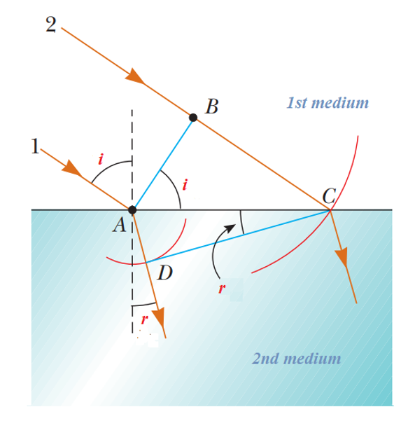
From DABC \displaystyle \sin i=\frac{{BC}}{{AC}} and from DADC \displaystyle \sin r=\frac{{AD}}{{AC}}.
If we divide sini and sinr we get
\displaystyle \frac{{\sin i}}{{\sin r}}=\frac{{{{BC}}/{{AC}}\;}}{{{{AD}}/{{AC}}\;}}
\displaystyle \Rightarrow \text{ }\frac{{\sin i}}{{\sin r}}=\frac{{BC}}{{AD}}
here \displaystyle BC={{v}_{1}}\times \Delta t\text{ and AD}={{v}_{2}}\times \Delta t
therefore
\displaystyle \frac{{\sin i}}{{\sin r}}=\frac{{BC}}{{AD}}=\frac{{{{v}_{1}}\times \Delta t}}{{{{v}_{2}}\times \Delta t}}
or
\displaystyle \frac{{\sin i}}{{\sin r}}=\frac{{{{v}_{1}}}}{{{{v}_{2}}}} ….(a)
we know that refractive index of any medium is given by
\displaystyle \mu =\frac{{c\text{ }(speed\text{ of light in vacuum)}}}{{v\text{ (speed of light in given medium)}}}
hence if \displaystyle {{\mu }_{1}} and \displaystyle {{\mu }_{2}}be the R.I. of the two mediums with respect to vacuum then
\displaystyle {{\mu }_{1}}=\frac{c}{{{{v}_{1}}}}\text{ or }{{v}_{1}}=\frac{c}{{{{\mu }_{1}}}}
\displaystyle similarly\text{ }{{\mu }_{2}}=\frac{c}{{{{v}_{2}}}}\text{ or }{{v}_{2}}=\frac{c}{{{{\mu }_{2}}}}
using \displaystyle {{v}_{1}}and \displaystyle {{v}_{2}} in equation (a)
i.e. \displaystyle \frac{{\sin i}}{{\sin r}}=\frac{{{{v}_{1}}}}{{{{v}_{2}}}} we get
\displaystyle \frac{{\sin i}}{{\sin r}}=\frac{{{{v}_{1}}}}{{{{v}_{2}}}}=\frac{{{c}/{{{{\mu }_{1}}}}\;}}{{{c}/{{{{\mu }_{2}}}}\;}}
hence \displaystyle \frac{{\sin i}}{{\sin r}}=\frac{{{{\mu }_{2}}}}{{{{\mu }_{1}}}}
Or
\displaystyle {{\mu }_{1}}\times \sin i={{\mu }_{2}}\times \sin r (which is Snell’s law of refraction)
Diffraction
If an opaque obstacle (or aperture) is placed between a source of light and a screen, in according with rectilinear propagation of light, a sharp shadow (or an illuminated) region is obtained on the screen as shown in figures.
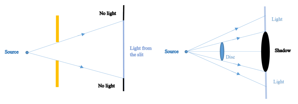
Grimaldi of Italy in the 17th century discovered that if the size of an obstacle or aperture is comparable with the wavelength of light, light deviates from rectilinear propagation near the edges of the obstacle (or aperture) and enters the geometrical shadow. This flaring out of light in the shadow zone as it passes obstacles or through small apertures is called diffraction.
Types of diffraction
The diffraction phenomenon is divided into two types:
Fresnel diffraction:
In this case of diffraction if either source or screen or both are at finite distance from the diffracting device [obstacle or aperture], the diffraction is called Fresnel type. Due to this spherical wave fronts reach the slit / diffracting device
Fraunhofer diffraction:
In this case, both source and screen are effectively at infinite distance from the diffracting device and pattern is the image of source modified by diffraction effects. Due to infinite distance of the source ,the wavefront reaching the slit/diffracting device is a plane wave front.
Fraunhofer diffraction by a single slit

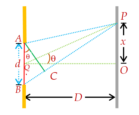
Let us analyze the diffraction pattern produced by plane waves passing through a single slit. We may note that a given slit or an aperture, howsoever small or narrow it will have a finite size. According to Huygen’s principle, every point on the wave front passing through the slit acts as a source of secondary wavelets. The fact gives rise to an interference between wavelets from various regions or point sources of the same wave front or slit.
Figure represents an enlarged diagram of narrow slit of width, d (taken from the above figure). Let us assume that as the plane wave-front AB (shown by red line with center at Q) reaches the slit, all points on it emit the secondary wavelets in the same phase. Thus if the disturbance is observed at point P on the far side of the slit at angle \displaystyle \theta to the normal, then there is a net path difference of \displaystyle \Delta x=BC=dsin\theta between the waves from the two edges of the slit AB.
\displaystyle \phi =\frac{{2\pi }}{\lambda }(\Delta x)
The main difference between young’s double slit pattern and Fraunhofer single slit pattern is that condition of maxima and minima are opposite.
Hence for minima or dark fringe path difference \displaystyle \Delta x should be integral multiple of \displaystyle \lambda .
Hence \displaystyle \Delta x=n\lambda
or \displaystyle dsin\theta =n\lambda
or
\displaystyle \sin \theta =\frac{{n\lambda }}{d} from diagram in \displaystyle \Delta OPQ \displaystyle \tan \theta =\frac{x}{D} if \displaystyle \theta is very small then \displaystyle sin\theta =\tan \theta
hence
\displaystyle \frac{{n\lambda }}{d}=\frac{x}{D}
\displaystyle x=\frac{{n\lambda D}}{d}
where as for bright fringe
\displaystyle d\sin \theta =(2n+l)\frac{\lambda }{2} Þ \displaystyle \sin \theta =(2n+1)\frac{\lambda }{{2d}}
From the figure \displaystyle \tan \theta =\frac{x}{D}. If \displaystyle \theta is very small \displaystyle \tan \theta=\sin\theta
hence \displaystyle \frac{x}{D}=(2n+1)\frac{\lambda }{{2d}}
Þ \displaystyle x=(2n+1)\frac{{\lambda D}}{{2d}}.
Also it is found that distribution of light on the screen is given by
\displaystyle I={{I}_{0}}\frac{{{{{\sin }}^{2}}\alpha }}{{{{\alpha }^{2}}}}
When \displaystyle \alpha =\pi \sin \theta /\lambda
The plot of intensity on screen is given in figure
The central peak in the intensity curve is called the primary maximum, while the other peaks are called secondary maximum. The height of the primary maximum is much more than any of the secondary maxima.
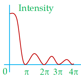
For finding the positions of various maxima lying in between the different minima, we have to differentiate the function \displaystyle \frac{{\sin \alpha }}{\alpha } with respect to a and equate that to zero. An elaborate calculation shows that these maxima, also called the secondary maxima, appear at values of \displaystyle \alpha =1.429\pi ,\text{ }2.459\pi ,\text{ }3.471\pi etc. (The details of this calculation will be given in our course on optics). The graph shows that the intensity is maximum at central maxima and as we go away from it the intensity falls for other secondary maximas. The heights of these secondary maxima are 1/21, 1/61, 1/120 respectively of the central maxima.
The angular spread of the intensity curve is given by
\displaystyle \sin \theta =\frac{\lambda }{d}
This shows that as the wavelength \displaystyle \lambda increases, or the width of the slit decreases, the angular spread increases. That is, the narrower the slit, the wider the diffraction pattern. Similarly, the greater the wavelength, the more widely spread is the pattern.
Width of central maximum:
The width of central maxima is the distance between first secondary minima on either side of O. If P is the position of \displaystyle {{1}^{{st}}} secondary minimum and OP = x, then from (1)
d\sin \theta =n\lambda here n=1
therefore \sin \theta =\lambda /d …(2)
If f is focal length of lens \displaystyle {{L}_{2}} which is held very close to the slit, then f = D = distance of the slit from the screen.
If \displaystyle \theta is small, \sin \theta \approx \theta =\frac{x}{f}=\frac{x}{D}
\displaystyle \theta is obviously half the angular width of central maxima of diffraction pattern of single slit.
From (2), \frac{x}{D}=\frac{\lambda }{d}
or, x=\frac{{D\lambda }}{d}
Width of central maxima \displaystyle =2x=\frac{{2D\lambda }}{d}=\frac{{2f\lambda }}{d}
This relation revels that as the slit width (d) increases, width of central maxima decreases.
Fresnel Distance
From the theory of diffraction of light at a single slit, the angle of diffraction (bending) for central maxima/first minima is
\theta =\sin \theta =\frac{\lambda }{d}
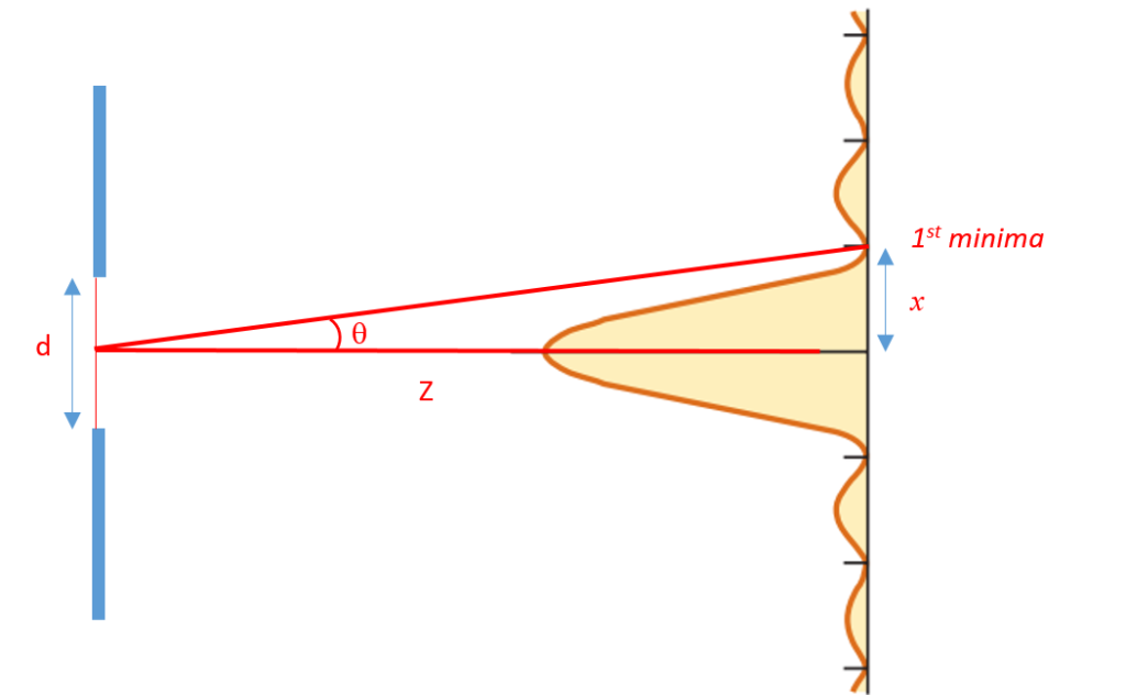
If \displaystyle \theta is small then
\begin{array}{l}\theta =\frac{x}{Z}\text{ (from the figure)}\\\Rightarrow \text{ }x=Z\theta \end{array}
so as the screen is taken away from the slit i.e. Z increases the value of half angular width (x) also increases
Therefore In traveling a distance Z, the half angular width (x) of beam would be given by
x=\left( {\frac{{Z\lambda }}{d}} \right)
At a particular distance of screen (Z) the beam width will become more than width of the slit (d) i.e.
\frac{{Z\lambda }}{d}\ge d only when Z\ge \frac{{{{d}^{2}}}}{\lambda }.
We call \frac{{{{d}^{2}}}}{\lambda }={{Z}_{F}}, the Fresnel distance.
Fresnel distance is the minimum distance a beam of light has to travel before its deviation from straight-line path becomes significant. In other words it is that distance travelled by light upto which no significant broadening/deviation of light is observed.
Resolving power of a slit
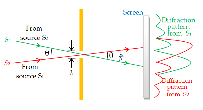
The resolving power of a slit, as defined by Lord Rayleigh, is the minimum angle subtended by two incident waves, comes in different directions from two distant point sources, that will permit their respective diffraction patterns to be distinguished. When waves coming from two distant sources \displaystyle {{S}_{1}} and \displaystyle {{S}_{2}} pass through the same circular slit in two directions, making an angle \displaystyle \theta (figure), the diffraction patterns of the two sets of waves are superposed. They begin to be distinguishable when the central maximum of one falls on the first zero on either side of the central maximum of the other, as indicated on the right in figure.
\displaystyle \theta =\frac{\lambda }{b}
which gives the resolving power of the slit according to Rayleigh’s definition.
Illustration
A parallel beam of monochromatic light of wavelength 450 nm passes through a long slit of width 0.2 mm. Find the angular divergence in which most of the light is diffracted.
Solution
Most of the light is diffracted between the two first order minima. These minima occur at angle given by
\displaystyle dsin\theta =\pm \lambda
or \displaystyle sin\theta = \displaystyle \pm \frac{\lambda }{d}
= \displaystyle \pm \frac{{450\times {{{10}}^{{-9}}}m}}{{0.2\times {{{10}}^{{-3}}}m}}=2.25\times {{10}^{{-3}}}
or \displaystyle \theta \simeq \pm 2.25\times {{10}^{{-3}}}\text{rad}
The angular divergence = \displaystyle 4.5\times{{10}^{{3}}} rad.
Illustration
A single slit is illuminated with a parallel beam of light of wavelength 5890 \displaystyle {{A}^{o}} and a diffraction pattern is obtained on a screen 1.2 m from the slit. The distance between positions of zero intensity on both sides of central maximum is found to be 3.5mm. Find the
(a) width of slit
(b) angle of diffraction for third order bright fringe (c) angular width of the third order bright fringe, assuming small angles of diffraction.
Solution
Given \displaystyle \lambda = 5890 \displaystyle {{A}^{o}} = \displaystyle \text{5890}\times {{10}^{{10}}}m D = 1.2 m
(a) Distance between positions of zero intensity on both sides of central maximum is also the width of central maximum. Here it is 3.5 mm, i.e., \displaystyle \text{3.5}\times {{10}^{{-3}}} m
Width of central maximum = \displaystyle \frac{{2\lambda D}}{d}
\ \displaystyle 3.5\times {{10}^{{-3}}}=\frac{{2\times 5890\times {{{10}}^{{-10}}}\times 12}}{d}
d = 0.0004 m
\ Width of slit d = 0.3 mm
\displaystyle dsin\theta =4\lambda
\displaystyle {{3}^{{rd}}} bright fringe is formed between third and fourth minima.
For \displaystyle {{3}^{{rd}}} bright fringe
\displaystyle d\sin \theta =\frac{{3\lambda +4\lambda }}{2}=\frac{{7\lambda }}{2}
\ \displaystyle \sin \theta =\frac{{7\lambda }}{{2d}}
= \displaystyle \frac{{7\times 5890\times {{{10}}^{{-10}}}}}{{2\times 0.4\times {{{10}}^{{-3}}}}} [d = \displaystyle 0.4\times {{10}^{{-3}}}m]
= 0.0051
\displaystyle \therefore \theta ={{0.29}^{o}}
Illustration
Compute the radius of the central disk of the diffraction pattern observed in a plant at the focus of a lens with a diameter of 2 cm and a focal length of 40 cm. Assume the lens is illuminated with a beam of parallel monochromatic light of wavelength \displaystyle 5.9\times {{10}^{{-7}}}m.
Solution
When we use equation, the angle subtended by the central disk in the diffraction pattern is
\displaystyle \theta =1.22\times \frac{{5.9\times {{{10}}^{{-7}}}m}}{{2\times {{{10}}^{{-2}}}m}}=3.60\times {{10}^{{-5}}}rad=7.4{2}”
Illustration
Two point sources of light are 50 cm apart. There are viewed by the eye at a distance L. The entrance opening (pupil) of the viewer’s eye has a diameter of 3.0 mm. If the eye were perfect, the limiting factor for resolution of the two sources would be diffraction. In that limit, how large could we make L and still have the sources seen as separate entities?
Solution
In the limiting case, \displaystyle \theta ={{\theta }_{c}} where \displaystyle \sin {{\theta }_{c}}=\frac{{1.22\lambda }}{D} (for circular aperture).But, we see from the figure that \displaystyle \sin {{\theta }_{c}} is nearly equal to s/L, because s is so much smaller than L. Substitution of this value gives
\displaystyle L\,\,\approx \,\,\frac{{sD}}{{1.22\,\,\lambda }}\,\,\approx \,\,\frac{{(0.50\,\,m)\,\,(3.0\times \,{{{10}}^{{-3}}}\,m)}}{{(1.22)\,\,(5.0\times {{{10}}^{{-7}}}\,\,m)}}\,=\,\,2.5 km
We have taken \displaystyle \lambda = 500 nm, about the middle of the visible range.
Polarisation of Light
The phenomenon of restricting the vibrations of light (electric vector) in a particular direction perpendicular to the direction of wave motion is called polarization of light.
Thus electromagnetic waves are said to be polarized when their electric field vectors are all in a single plane called the plane of oscillation/vibration.

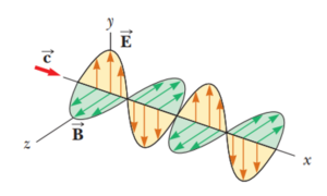
The diagram shows a polarized light wave or electromagnetic wave having all electric fields \displaystyle (\vec{E})
in x-y plane shown by red arrows. Hence the plane of oscillations is x-y plane. Whereas a plane perpendicular to the vibrations \displaystyle (\vec{E}) and containing the direction of propagation (which is x axis in this case) is called plane of polarization. Here in this diagram it is x-z plane.
Note that in the diagram given below the plane ABCD in which the vibrations of polarized light are confined is called the plane of vibration. The plane KLMN which is perpendicular to the plane of vibration is defined as the plane of polarization.
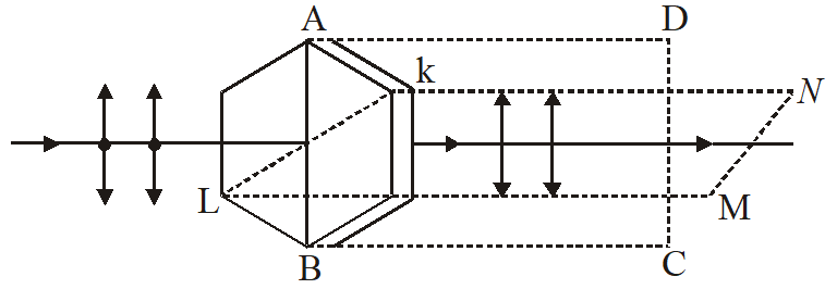
Light waves from common sources are unpolarized. The most common technique for producing polarized light is to use a material that transmits waves whose electric fields vibrate in a plane parallel to a certain direction and that absorbs waves whose electric fields vibrate in all other directions. On this principle sheet containing long chain of hydrocarbons are made which have large electrical conductivity in one direction. Example of which is PVA (Polyvinyl alcohol)
When originally unpolarized light is passed through a polariser, the transmitted intensity is half of the original intensity. In actual practice, the transmitted intensity may be even somewhat less than half of the original intensity.
Law of Malus
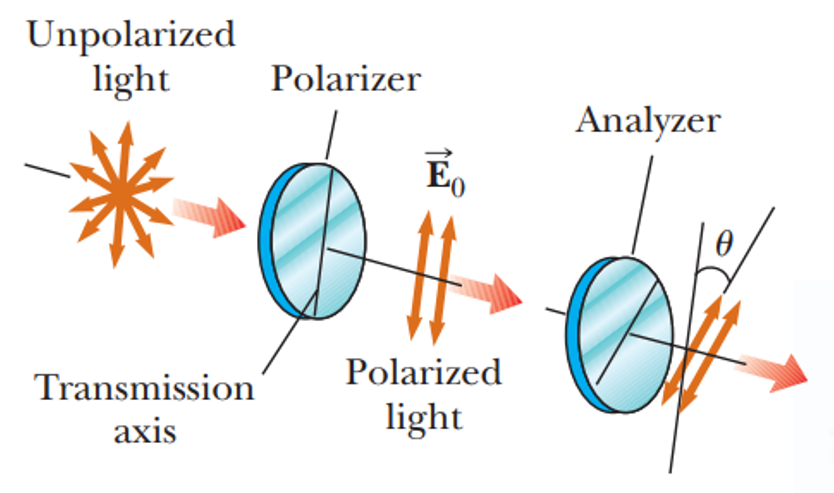
According to law of Malus, when a beam of completely plane polarized light is incident on an analyzer, the resultant intensity of light (I) transmitted is directly proportional to the square of the cosine of the angle ( \displaystyle \theta ) between the plane of transmission axis of analyzer and polarizer.
i.e. I\propto {{\cos }^{2}}\theta
This rule is also called cosine squared rule, and we can use it only when the light reaching a polarizing sheet is already polarized. The transmitted intensity I is maximum and equal to the original intensity \displaystyle {{I}_{o}} when the original wave is polarized parallel to the polarizing direction of the sheet (i.e. \displaystyle \theta ={{0}^{o}}={{180}^{o}}). I is zero, when the original wave is polarized perpendicular to the polarizing direction of the sheet (i.e. when \displaystyle \theta ={{90}^{o}}).
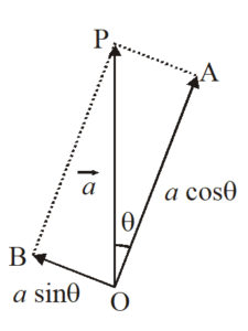
To prove this law, suppose \vec{a} is amplitude of electric vector transmitted by the polarizer along OP. The plane of analyzer OA makes an angle \displaystyle \theta with OP as shown in figure below. The two rectangular components of \vec{a} are ( \displaystyle acos\theta ), parallel to plane of transmission of analyzer, and ( \displaystyle asin\theta ), perpendicular to plane of transmission of analyzer.
As the component transmitted through analyzer is only \displaystyle acos\theta ,therefore, intensity of light transmitted from analyzer is
I=k{{(a\cos \theta )}^{2}}=k{{a}^{2}}{{\cos }^{2}}\theta
I={{I}_{0}}{{\cos }^{2}}\theta
where {{I}_{0}}=k{{a}^{2}}=intensity of light transmitted from polarizer which is constant.
Hence I\propto {{\cos }^{2}}\theta , which proves the law of Malus.
When polarizer and analyzer are parallel,
either \displaystyle \theta ={{0}^{o}} or \displaystyle {{180}^{o}} so that \cos \theta =\pm 1
\ I={{I}_{0}}
When polarizer and analyzer are perpendicular to each other, \theta =90{}^\circ ;
\cos \theta =\cos 90{}^\circ =0
\ I = 0.
Illustration
At what angle should the axes of two polaroids be placed so as to reduce the intensity of incident upolarised light to 1/3.
Solution:
According to the law of Malus I={{I}_{0}}{{\cos }^{2}}\theta
\Rightarrow {{\cos }^{2}}\theta =\frac{I}{{{{I}_{0}}}}=\frac{1}{3}
\Rightarrow \cos \theta =\frac{1}{{\sqrt{3}}}=\frac{{\sqrt{3}}}{{\sqrt{3}\sqrt{3}}}
or \cos \theta =\frac{{1.732}}{3}=0.5773
or \theta =54.7{}^\circ
Polarisation of Light by Reflection
When unpolarised light is reflected from a surface, the reflected light may be completely polarised, partially polarised or unpolarised. This would depend on the angle of incidence.
If angle of incidence is \displaystyle {{0}^{o}} or \displaystyle {{90}^{o}}, the reflected beam remains unpolarised. For angles of incidence between \displaystyle {{0}^{o}} and \displaystyle {{90}^{o}}, the reflected beam is polarized to varying degree
The angle of incidence at which the reflected light is completely plane polarized is called polarising angle or Brewster’s angle. It is represented by \displaystyle {{i}_{p}}. The value of \displaystyle {{i}_{p}} depends on the wavelength of light used. Therefore, complete polarization is possible only for monochromatic
light. In figure unpolarised light is incident along AO at \displaystyle \angle {{i}_{p}} on the interface XY separating air from a medium of refractive index \displaystyle \mu . The light reflected along OB is completely plane polarised. The light refracted along OC continues to be unpolarised.
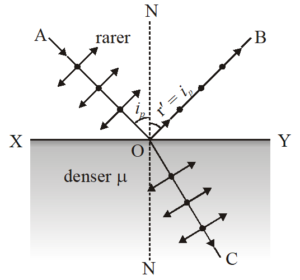
The reflected light, therefore, contains vibrations of electric vector perpendicular to the plane of incidence. Hence the reflected light is completely plane polarised in a direction perpendicular to the plane of incidence.
Brewster’s Law
According to this law, when unpolarised light is incident at polarising angle, \displaystyle {{i}_{p}} on an interface separating air from a medium of refractive index \displaystyle \mu , then the reflected light is fully polarized perpendicular to the plane of incidence, provided \mu =\tan {{i}_{p}}
This relation represents Brewster’s Law. Note that the parallel components of incident light do not disappear, but refract into the medium, with the perpendicular components.
It has been observed experimentally that when light is incident at polarising angle, the reflected component along OB and refracted component along OC are mutually perpendicular to each other.
Thus, in above figure. \angle \mathbf{BOY}+\angle \mathbf{YOC}=\mathbf{90}{}^\circ
or (90{}^\circ -{{i}_{p}})+(90{}^\circ -r)=90{}^\circ , where r is the angle of refraction.
\Rightarrow 90{}^\circ -{{i}_{p}}=r
According to Snell’s law, \mu =\frac{{\sin i}}{{\sin r}}
When i={{i}_{p}},r=(90{}^\circ -{{i}_{p}})
\ \mu =\frac{{\sin {{i}_{p}}}}{{\sin \,(90{}^\circ -{{i}_{p}})}}=\frac{{\sin {{i}_{p}}}}{{\cos {{i}_{p}}}}=\tan {{i}_{p}}
This proves Brewster’s law.
Illustration
A ray of light is incident on the surface of a glass plate of refractive index 1.536 at the polarizing angle. Calculate the angle of refraction.
Solution:
Since \tan {{i}_{p}}=\mu =1.536
\ {{i}_{p}}={{\tan }^{{-1}}}(1.536)=56{}^\circ 56\prime , r=90{}^\circ -{{i}_{p}}=90{}^\circ -56{}^\circ 56\prime =33{}^\circ 4\prime
Polaroids
A polaroids is a material which polarised light. Tourmaline is a natural polarising material. Polaroids are now artificially made. It was discovered that small needle shaped crystals of quinine idosulphate have the property of polarising the light. A number of these crystal with their axes parallel to one another are packed in between two sheets of plastic. Such a sheet serves as the Polaroid.
Uses of plane polarised light and polaroids
(i) The microscopic objectives are fitted with polaroids to avoid glare in observing very minute particles.
(ii) Polaroids are usefull in three dimensional motion pictures, i.e., in holography.
(iii) Polaroids are used to improve color contrast in old oil paintings.
(iv) Polarisation of scattered sunlight is used for navigation in solar regions, where magnetic compass becomes inoperative.
(v) By determining the polarising angle ( \displaystyle \angle {{i}_{p}}) and using Brewster’s law, the refractive index of dark transparent substance can be determined.
(vi) Polarisation is also used to study asymmetries in crystals and molecules using the phenomenon of optical activity.
Practice Questions (Basic Level)
1.
By corpuscular theory of light, the phenomenon which can be explained is
(a) Refraction
(b) Interference
(c) Diffraction
(d) Polarisation
Ans (a)
2.
According to corpuscular theory of light, the different colours of light are due to
(a) Different electromagnetic waves
(b) Different force of attraction among the corpuscles
(c) Different size of the corpuscles
(d) None of the above
Ans (c)
3.
Huygen’s conception of secondary waves
(a) Allow us to find the focal length of a thick lens
(b) Is a geometrical method to find a wavefront
(c) Is used to determine the velocity of light
(d) Is used to explain polarization
Ans (b)
4.
The idea of the quantum nature of light has emerged in an attempt to explain
(a) Interference
(b) Diffraction
(c) Radiation spectrum of a black body
(d) Polarisation
Ans (c)
5.
By a monochromatic wave, we mean
(a) A single ray
(b) A single ray of a single colour
(c) Wave having a single wavelength
(d) Many rays of a single colour
Ans (c)
6.
By Huygen’s wave theory of light, we cannot explain the phenomenon of
(a) Interference
(b) Diffraction
(c) Photoelectric effect
(d) Polarisation
Ans (c)
7.
Wavefront means
(a) All particles in it have same phase
(b) All particles have opposite phase of vibrations
(c) Few particles are in same phase, rest are in opposite phase
(d) None of these
Ans (a)
8.
Wavefront of a wave has direction with wave motion
(a) Parallel
(b) Perpendicular
(c) Opposite
(d) At an angle of q
Ans (b)
9.
Which one of the following phenomena is not explained by Huygen’s construction of wavefront
(a) Refraction
(b) Reflection
(c) Diffraction
(d) Origin of spectra
Ans (d)
10.
Which one of the following phenomena is not explained by Huygen’s construction of wavefront
(a) Refraction
(b) Reflection
(c) Diffraction
(d) Origin of spectra
Ans (d)
11.
Huygen’s principle of secondary wavelets may be used to
(a) Find the velocity of light in vacuum
(b) Explain the particle behaviour of light
(c) Find the new position of the wavefront
(d) Explain photoelectric effect
Ans (c)
12.
Select the right option in the following
(a) Christian Huygens a contemporary of Newton established the wave theory of light by assuming that light waves were transverse
(b) Maxwell provided the compelling theoretical evidence that light is transverse wave
(c) Thomas Young experimentally proved the wave behaviour of light and Huygens assumption
(d) All the statements give above, correctly answers the question “what is light”
Ans (b)
13.
A slit of width a is illuminated by white light. For red light (l = 6500 Å), the first minima is obtained at \theta ={{30}^{o}}. Then the value of a will be
(a) 3250 Å
(b) 6.5\times {{10}^{{-4}}}mm
(c) 1.24 microns
(d) 2.6\times {{10}^{{-4}}}cm
Ans (c)
14.
The light of wavelength 6328 Å is incident on a slit of width 0.2 mm perpendicularly, the angular width of central maxima will be
(a) {{0.36}^{o}}
(b) {{0.18}^{o}}
(c) {{0.72}^{o}}
(d) {{0.09}^{o}}
Ans (a)
15.
The bending of beam of light around corners of obstacles is called
(a) Reflection
(b) Diffraction
(c) Refraction
(d) Interference
Ans (b)
16.
The penetration of light into the region of geometrical shadow is called
(a) Polarisation
(b) Interference
(c) Diffraction
(d) Refraction
Ans (c)
17.
A slit of size 0.15 cm is placed at 2.1 m from a screen. On illuminated it by a light of wavelength 5 ´ 10–5 cm. The width of central maxima will be
(a) 70 mm
(b) 0.14 mm
(c) 1.4 mm
(d) 0.14 cm
Ans (c)
18.
A diffraction is obtained by using a beam of red light. What will happen if the red light is replaced by the blue light
(a) Bands will narrower and crowd full together
(b) Bands become broader and further apart
(c) No change will take place
(d) Bands disappear
Ans (a)
19.
Conditions of diffraction is
(a) \frac{a}{\lambda }=1
(b) \frac{a}{\lambda }>>1
(c) \frac{a}{\lambda }<<1
(d) None of these
Ans (a)
20.
Which statement is correct for a zone plate and a lens
(a) Zone plate has multi focii whereas lens has one
(b) Zone plate has one focus whereas lens has multiple focii
(c) Both are correct
(d) Zone plate has one focus whereas a lens has infinite
Ans (a)
21.
In Fresnel diffraction, if the distance between the disc and the screen is decreased, the intensity of central bright spot will
(a) Increase
(b) Decrease
(c) Remain constant
(d) None of these
Ans (b)
22.
A plane wavefront (\lambda =6\times {{10}^{{-7}}}m) falls on a slit v wide. A 0.4\,mmconvex lens of focal length 0.8\,m placed behind the slit focusses the light on a screen. What is the linear diameter of second maximum
(a) 6\,mm
(b) 12\,mm
(c) 3\,mm
(d) 9\,mm
Ans (a)
23.
A zone plate of focal length 60\,cm, behaves as a convex lens, If wavelength of incident light is 6000\,\,{\AA}, then radius of first half period zone will be
(a) 36\times {{10}^{{-8}}}m.
(b) 6\times {{10}^{{-8}}}m.
(c) \sqrt{6}\times {{10}^{{-8}}}m.
(d) 6\times {{10}^{{-4}}}m.
Ans (d)
Practice Questions (JEE Main Level)
1.
A parallel monochromatic beam of light is incident normally on a narrow slit. A diffraction pattern is formed on the screen placed perpendicular to the direction of incident beam. At the first minimum of the diffraction pattern, the phase difference between the rays coming from the two edges of the slit is
(a) Zero
(b) \displaystyle \frac{\pi }{2}
(c) \displaystyle \pi
(d) 2 \displaystyle \pi
Ans :d
2.
A slit of width d is placed in front of a lens of focal length 0.5 m and is illuminated normally with light of wavelength 5.89 × 10–-7m. The first diffraction minima on either side of central diffraction maximum are separated by 2×10⁻³ m. The width d of the slit is
(a) 5.89 × 10⁻⁴ m
(b) 2.945 × 10⁻⁴ m
(c) 1.178 × 10⁻³ m
(d) 1.4725 × 10⁻⁴ m
Ans : b
3.
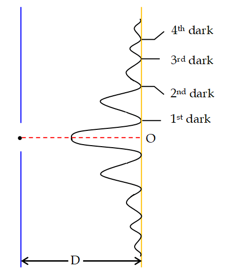
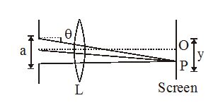
In a single slit diffraction experiment, as shown in fig, I0 is intensity at O corresponding to \displaystyle \theta = 0°. Then intensity at P, I( \displaystyle \theta ) if \displaystyle \lambda is the wavelength of light used is
(a) \displaystyle I(\theta )\,=\,{{I}_{o}}\,\left\{ {\frac{{\sin \left( {\frac{{\pi a\,\sin \,\theta }}{\lambda }} \right)}}{{\frac{{\pi a\,\sin \,\theta }}{\lambda }}}} \right\}
(b) \displaystyle I(\theta )\,=\,{{I}_{o}}\,{{\left\{ {\frac{{\sin \left( {\frac{{\pi a\,\sin \,\theta }}{\lambda }} \right)}}{{\frac{{\pi a\,\sin \,\theta }}{\lambda }}}} \right\}}^{2}}
(c) \displaystyle I(\theta )\,=\,{{I}_{o}}\,\left\{ {\frac{{\sin \left( {\frac{{a\,\sin \,\theta }}{\lambda }} \right)}}{{\frac{{\pi a\,\sin \,\theta }}{\lambda }}}} \right\}
(d) \displaystyle I(\theta )\,=\,{{I}_{o}}\,\left\{ {\frac{{{{{\sin }}^{2}}\left( {\frac{{a\,\sin \,\theta }}{\lambda }} \right)}}{{\frac{{a\,\sin \,\theta }}{\lambda }}}} \right\}
Ans : b
4.
A beam of light of wavelength 600 nm from a distant source falls on a single slit 1 mm wide and the resulting diffraction pattern is observed on a screen 2 m away. The distance between the first dark fringes on either side of the central bright fringe is
(a) 1.2 cm
(b) 1.2 mm
(c) 2.4 cm
(d) 2.4 mm
Ans : d
5.
When the diffraction pattern from a certain slit illuminated with laser light ( \displaystyle \lambda = 6660Å) is projected on a screen 150 cm from the slit, the second minima on each side are separated by 8 cm. This tells us that
(a) the slit is approximately 0.005 cm wide
(b) the slit is approximately 0.05 cm wide.
(c) the slit is approximately 0.0025 cm wide
(d) the slit is approximately 0.025 cm wide.
Ans : a
6.
Diffraction occurs for all types of waves, including sound waves. High-frequency sound from a distant source with wave length 9.00 cm passes through a narrow slit 12.0 cm wide. A microphone is placed 40.0 cm directly in front of the center of the slit, corresponding to point O in figure. The microphone is then moved in a direction perpendicular to the line from the centre of the slit to point O. At what distances from O will the intensity detected by the microphone be zero?
(a) 44.5 cm
(b) –47.6 cm
(c)± 45.4 cm
(d) 42.7 cm
Ans : c
7.
Red light of wavelength 633 nm from a helium-neon laser passes through a slit 0.350 mm wide. The diffraction pattern is observed on a screen 3.00 m away. Define the width of a bright fringe as the distance between the minima on either side. (a) What is the width of the central bright fringe?
(a) 10.8 mm
(b) 11.6 mm
(c) 12.4 mm
(d) 13.5 mm
Ans : a
8.
Monochromatic light from a distant source is incident on a slit 0.750 mm wide. On a screen 2.00 m away, the distance from the central maximum of the diffraction pattern to the first minimum is measured to be 1.35 mm. Calculate the wavelength of the light.
(a) 506 nm
(b) 605 nm
(c) 504 nm
(d) 306 nm
Ans : a
9.
Unpolarised light falls on two polarizing sheets placed one over another. What must be the angle between their transmission axes if the intensity of light transmitted finally is one-third the intensity of the incident light? Assume that each polarizing sheet acts as an ideal polarizer.
(a) \displaystyle {{\cos }^{{-1}}}[\sqrt{{2/3}}]
(b) \displaystyle {{\cos }^{{-1}}}[\sqrt{{2/3}}]
(c) \displaystyle {{\cos }^{{-1}}}[\sqrt{{2/3}}]
(d) \displaystyle {{\cos }^{{-1}}}[\sqrt{{2/3}}]
Ans : a
2.
Unpolarized light of intensity 20.0 W/cm2 is incident on two polarizing filters. The axis of the first filter is at an angle of 25.0° counterclockwise from the vertical (viewed in the direction the light is traveling) and the axis of the second filter is at 62.0 counterclockwise from the vertical. What is the intensity of the light after it has passed through the second polarizer?
(a) 5.38 \displaystyle W/{{m}^{2}}
(b) 6.38 \displaystyle W/{{m}^{2}}
(c) 4.48 \displaystyle W/{{m}^{2}}
(d) 6.8 \displaystyle W/{{m}^{2}}
Ans : b
10.
Three polarizing filters are stacked, with the polarizing axis of the second and third filters at 23.0° and 62.0, respectively, to that of the first. If unpolarized light is incident on the stack, the light has intensity 75.0 W/cm2 after it passes through the stack. If the incident intensity is kept constant, what is the intensity of the light after it passed through the stack if the second polarizer is removed
(a) 34.2 \displaystyle W/{{m}^{2}}
(b) 43.2 \displaystyle W/{{m}^{2}}
(c) 32.3 \displaystyle W/{{m}^{2}}
(d) 42.3 \displaystyle W/{{m}^{2}}
Ans : c
Practice Questions (JEE Advance Level)
Lorem ipsum dolor sit amet, consectetur adipiscing elit. Ut elit tellus, luctus nec ullamcorper mattis, pulvinar dapibus leo.
