Video Lecture
Theory For Making Notes
Measuring Instruments
Galvanometer
A galvanometer detects the presence of current in the branch where it is connected.
It is the basic instrumentused in making various meters, such
(i)
ammeter (measures current)
(ii)
voltmeter(measures voltage or potential difference)
(iii)
ohmeters(measures resistance)
(iv)
powermeter (measures power)
A galvanometer can detect a current as low as 10–9 A.
- In DC circuits, usually moving coiltype galvanometers are used. Its deflection is directly proportional to the current that passes through it, or
I∝ q or I = Kθ
where K is called galvanometer constant.
- The deflection per unit current is called current sensitivity of the galvanometer,
CS=\frac{\theta }{I}=\frac{1}{K}
Shunting a galvanometer decreases its sensitivity. (When a small resistance is connected in parallel with a large resistance, we say that the large resistance is shunted).
- The total resistance of the galvanometer between its two terminals is called galvanometer resistance and is represented by G.
- The total resistance of the galvanometer between its two terminals is called galvanometer resistance and is represented by G.
- The current required for full-scale deflection in a galvanometer is called full-scale deflection current and is represented by Ig.
Ammeter
An ammeter is an instrument which reads the current passing through it. The ammeter must be inserted into the branch so that the current to be measured passes through it. That is, an ammeter is connected in series with the element through which current is to measured.
- The reading of an ammeter is always lesser than the actual current in the circuit. If V is the potential difference across a resistance R, the true current is I = (V/R). However, when an ammeter of resistance r is used to measure it, the reading will be
{I}’=\frac{V}{{(R+r)}}
which is less than the true current I.
- Smaller the resistance of an ammeter, the more accurate will be its reading. An ammeter is said to be ideal if its resistance (r) is zero. However, ideal ammeter cannot be realized in practice.
Conversion of a Galvanometer into an Ammeter
To convert a galvanometer into an ammeter of a certain range, say Io, a small resistance S (called shunt) is connected in parallel with the galvanometer. The range means the upper limit of the quantity which can be measured by the instrument. The value of S is chosen such that the current passing through the galvanometer of resistance G becomes equal to its full-scale deflection value Ig. Thus, equating the potential difference across two parallel branches, we have
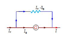
IgG = (Io – Ig)S
or S=\frac{{{{I}_{g}}}}{{\text{(}{{I}_{o}}\text{ }-\text{ }{{I}_{g}})}}G
Illustration
What is the value of shunt which passes 10% of the main current through a galvanometer of 99 ohms.
Solution
As the shunt is a small resistance S in parallel with a galvanometer (of resistance G)
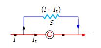
(I – Ig)S = Ig*G
or \displaystyle S=\frac{{{{I}_{g}}G}}{{(I-{{I}_{g}})}}
Here, G = 99 Ω and
Ig = (10/100) I = 0.1I
\displaystyle S=\frac{{0.1I\times 99}}{{(I-0.1\,I)}}=\frac{{0.1}}{{0.9}}\times 99 = 11 Ω
Voltmeter
A voltmeter is an instrument which reads the potential difference across its terminals. To measure the potential difference between any two points A and B in the circuit, the voltmeter terminals are connected to A and B without breaking the circuit.
- The reading of a voltmeter is always lesser than the true value. If a current Io is passing through a resistance R, the true value V = IoR. However, when a voltmeter having resistance r is connected across R, the current through R will become
{I}’=\frac{r}{{(R+r)}}{{I}_{o}}
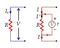
and so {V}’={I}’R=\frac{V}{{[1+(R/r)]}}
When the voltmeter is connected across R, its reading will also be V’ which is less than V.
- Greater the resistance of voltmeter, the more accurate will be its reading. A voltmeter is said to be idealif its resistance r is infinite. An ideal voltmeter draws no current from the circuit element for its operation.
Conversion of a Galvanometer into a Voltmeter
To convert a galvanometer into a voltmeter of certain range, say V, a high resistance R is connected in series with the galvanometer. The value of R is chosen such that the current passing through the galvanometer of resistance G becomes equal to its full-scale deflection value Ig. Thus, we should have
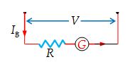
V = Ig(G + R)
or R=\frac{V}{{{{I}_{g}}}}-\text{ }G
Illustration
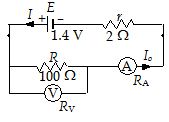
A battery of emf 1.4 V and internal resistance 2 Ω is connected to a resistor of 100 Ω. In order to measure the current through the resistance and the potential difference across its ends, an ammeter is connected in series with it and a voltmeter is connected across its ends. The resistance of the ammeter is 4/3 Ω and that of the voltmeter is 200 Ω. What are the readings of the two instruments ? What would be their reading if they were ideal instruments ?
Solution
Let RA and RV be the resistances of the ammeter and voltmeter respectively. Then the total resistance across the emf E is
Req = \displaystyle \frac{{R{{R}_{V}}}}{{R+{{R}_{V}}}}+{{R}_{A}}+r=\frac{{100\times 200}}{{100+200}}+\frac{4}{3}+2 = \displaystyle \frac{{210}}{3}Ω
Therefore, the current
{{I}_{o}}=\frac{E}{{{{R}_{{eq}}}}}=\frac{{1.4}}{{(210/3)}}= 0.02 A
This is the current through ammeter. Hence, the reading of ammeter is 0.02 A.
Reading of voltmeter = pd across its terminals
= {{I}_{o}}\left( {\frac{{R{{R}_{V}}}}{{R+{{R}_{V}}}}} \right)=0.02\left( {\frac{{100\times 200}}{{100+200}}} \right)= 1.33 V
If the ammeter and the voltmeter were ideal, RA = 0 and RV= ¥. Then,
The reading of ammeter = \displaystyle \frac{E}{{r+R}}=\frac{{1.4}}{{2+100}}= 0.0137 A
The reading of voltmeter = {{I}_{o}}R=\frac{{1.4}}{{102}}\times 100 = 1.37 V
Wheat-stone Bridge
It is an arrangement of four resistances used for measuring unknown resistance in terms of other three known resistances.
Construction
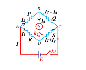
It consists of four resistances P, Q, R and S arranged in form of bridge. A source of emf E is connected between A and C and galvanometer is connected between B and D. Usually unknown resistance is put in place S.
Principle:
If there is no deflection in galvanometer on pressing key {{K}_{1}} and {{K}_{2}} , then Wheatstone Bridge is said to be balanced and ratio of P and Q is equal to the ratio of R and S
i.e., \frac{P}{Q}=\frac{R}{S}
Knowing, P, Q and R, the value of S can be calculated.
Proof:
Applying K.V.L in loop BDCB, we get
{{I}_{1}}.R-{{I}_{g}}G-{{I}_{2}}P=0 … (i)
Applying K.V.L in loop ADBA, we get
{{I}_{g}}G+({{I}_{1}}+{{I}_{g}})S-({{I}_{2}}-{{I}_{g}})Q=0 … (ii)
If bridge is balanced, then {{I}_{g}}=0
Hence, equation (i) and (ii) becomes
{{I}_{1}}.R={{I}_{2}}.P
and {{I}_{1}}.S={{I}_{2}}.Q
or \frac{P}{Q}=\frac{R}{S}
When this happens, the points B and D are at the same potential.
Also note that in the network, the cell arm and the galvanometer arm are interchangeable.
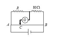
Illustration
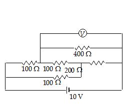
An electrical circuit is shown in the figure. Calculate the potential difference across the resistor of 400 ohm, as will be measured by the voltmeter of resistance 400 ohm, either by applying Kirchhoff’s rules or otherwise.
Solution
The equivalent resistance of the voltmeter and the 400Ω resistor in parallel is 200Ω . The circuit is a balanced Wheatstone bridge.
No current will flow through the 100 Ω-resistor connected between B and D.
Meter bridge: (Slide wire meter bridge)
It is used to measure unknown resistance and to compare unknown resistance of two conductors.
Principle:
It works on the principle of balanced wheatstone bridge i.e., \frac{P}{Q}=\frac{R}{S}
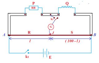
Working:
Close key {{k}_{1}} and then {{k}_{2}} , now move up Jockey (J) over the wire AB so that galvanometer shows no deflection.
If r is resistance per unit length of wire then resistance of portion l is R=l\,.\,r and resistance of portion (100-l) is S=(100-l)\,r . Therefore
\frac{R}{S}=\frac{l}{{(100-l)}} … (i)
and according to principle of wheatstone bridge
Hence, \frac{P}{Q}=\frac{R}{S}
or \frac{P}{Q}=\frac{l}{{(100-l)}} …(ii)
Hence Q=\frac{{(100-l)}}{l}\times P
If Q is nearly equal to P, balance point of the bridge will be near to middle of slide wire.
Errors
The major systematic errors in this experiment are due to the (i) heating effect, (ii) end corrections introduced due to shift of the zero of the scale at A and B, (iii) stray resistances in P and Q,
(iv) errors due to non-uniformity of the meter bridge wire.
Error analysis:
End corrections can be estimated by including known resistances P1 and Q1 in the two ends and finding the null point:
\displaystyle \frac{{{{P}_{1}}}}{{{{Q}_{1}}}} = \displaystyle \frac{{{{\ell }_{1}}+\alpha }}{{100-{{\ell }_{1}}+\beta }} (where a and b are the end corrections.)
When the resistance Q1 is placed in the left gap and P1 in the right gap,
\displaystyle \frac{{{{Q}_{1}}}}{{{{P}_{1}}}}=\frac{{{{\ell }_{2}}+\alpha }}{{100-{{\ell }_{2}}+\beta }} which gives two linear equations for finding a and b.
In order that a and b be measured accurately, P1 and Q1 should be as different from each other as possible.
For the actual balance point, \displaystyle \frac{P}{Q} = \displaystyle \frac{{\ell +\alpha }}{{100-\ell +\beta }} = \displaystyle \frac{{{{{{\ell }’}}_{1}}}}{{{{{{\ell }’}}_{2}}}} ,
Errors due to non-uniformity of the meter bridge wire can be minimised by interchanging the resistances in the gaps P and Q.
\displaystyle \frac{{\delta P}}{P}=\left| {\frac{{\delta {{{{\ell }’}}_{1}}}}{{{{{{\ell }’}}_{1}}}}} \right|+\left| {\frac{{\delta {{{{\ell }’}}_{2}}}}{{{{{{\ell }’}}_{2}}}}} \right| , where Δl’1 and Δl’2 are of the order of the least count of the scale.
The error is, therefore, minimum if l’1 = l’2 i.e. when the balance point is in the middle of the bridge. The error in ris \displaystyle \frac{{\delta \rho }}{\rho }=\frac{{2\delta r}}{r}+\frac{{\delta L}}{L}+\frac{{\delta P}}{P}
Illustration
Two unknown resistances X and Y are placed in the left and right gaps of a metre bridge. The null point in galvanometer is obtained at a distance of 80 cm from left. A resistance of 100 Ω is now connected in parallel across X. The null point is then found by shifting the sliding contact towards left by 20 cm. Calculate X and Y.
Solution
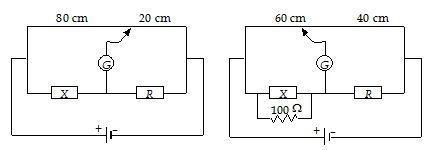
From first null point,
\displaystyle \frac{X}{Y}=\frac{{80}}{{20}} … (i)
From second null point,
\displaystyle \frac{{\left( {\frac{{100 X}}{{100+X}}} \right)}}{Y}=\frac{{60}}{{40}} …(ii)
From Eqn. (i) and (ii), we have
\displaystyle X=\frac{{500}}{3}\Omega \text{ }and\text{ }Y=\frac{{125}}{3}\Omega
Practice Questions (Basic Level)
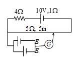
Q.1
In the circuit shown, a meter bridge is in its balanced state. The meter bridge wire has a resistance 0.1 ohm/cm. The value of unknown resistance X and the current drawn from the battery of negligible resistance is
(a) 6W, 5 amp
(b) 4W, 0.1 amp
(c) 4W, 1.0 amp
(d) 12W, 0.5 amp
Ans : c
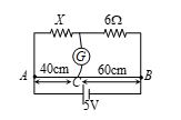
Q.2
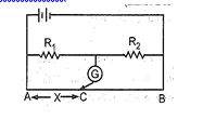
AB is a wire of uniform resistance. The galvanometer G shows zero current when the length AC= 20 cm and
CB = 80 cm. The resistance R is equal to
(a) 2 W
(b) 8 W
(c) 20 W
(d) 40 W
Ans. (c)
Q.3
In the shown arrangement of the experiment of the meter bridge if AC corresponding to null deflection of galvanometer is x, what would be its value if the radius of the wire AB is doubled?
(a) x
(b) x/4
(c) 4x
(d) 2x
Ans. (a)
Q.4
A galvanometer of resistance 19.5 W gives full scale deflection when a current of 0.5 ampere is passed through it. It is desired to convert it into an ammeter of full scale current 20 ampere. Value of shunt is
(a) 0.5 W (b) 1 W (c) 1.5 W (d) 2 W
Ans : (a)
Q.5
An ammeter is obtained by shunting a 30 W galvanometer with a 30W resistance. What additional shunt should be connected across it to double the range?
(a) 15 W (b) 10 W (c) 5 W (d) none of these
Ans : (a)
Q.6
A galvanometer of 10 ohm resistance gives full scale deflection with 0.01 ampere of current. It is to be converted into an ammeter for measuring 10 ampere current. The value of shunt resistance required will be
(a) \frac{{10}}{{999}}ohm
(b) 0.1 ohm
(c) 0.5 ohm
(d) 1.0 ohm
Ans : (a)
Practice Questions (JEE Main Level)
Q.1
A resistance 5 \displaystyle \Omega is connected in the left gap of a metre bridge and 15 \displaystyle \Omega in the other gap. The position of balancing point is :
(a) 10 cm
(b) 20 cm
(c) 25 cm
(d) 75 cm
Ans: (c)
Q.2
A moving coil galvanometer has 150 equal divisions. Its current sensitivity is 10 divisions per milliampere and voltage sensitivity is 2 divisions per millivolt. In order that each division reads 1 volt, the resistance in ohms needed to be connected in series with the coil will be :
(a) \displaystyle {{10}^{3}}
(b) \displaystyle {{10}^{5}}
(c) 99995
(d) 9995
Ans: (d)
Q.3
In a Wheat stone’s bridge, three resistances P, Q and R connected in the three arms and the fourth arm is formed by two resistanceand \displaystyle {{S}_{2}} connected in parallel. The condition for bridge to be balanced will be :
(a) \displaystyle \frac{P}{Q}\,=\,\frac{R}{{{{S}_{1}}+{{S}_{2}}}}
(b) \displaystyle \frac{P}{Q}\,=\,\frac{{2R}}{{{{S}_{1}}+{{S}_{2}}}}
(c) \displaystyle \frac{P}{Q}\,=\,\frac{{R\left( {{{S}_{1}}+{{S}_{2}}} \right)}}{{{{S}_{1}}{{S}_{2}}}}
(d) \displaystyle \frac{P}{Q}\,=\,\frac{{R\left( {{{S}_{1}}+{{S}_{2}}} \right)}}{{2{{S}_{1}}{{S}_{2}}}}
Ans: (c)
Q.4
A moving coil galvanometer of resistance 50 \displaystyle \Omega gives a full scale deflection when a current of 0.5 mA is passed through it. To convert it to a voltmeter of range 10V, the resistance required to be placed in series is :
(a) 10000 \displaystyle \Omega
(b) 1995 \displaystyle \Omega
(c) 1950 \displaystyle \Omega
(d) 2000 \displaystyle \Omega
Ans: (b)
Q.5
A galvanometer of resistance 20 \displaystyle \Omega gives a full scale deflection with a current of 2mA. What resistance should be connected in parallel so that it may measure 2A on full scale deflection ?
(a) 0.2 \displaystyle \Omega
(b) 0.4 \displaystyle \Omega
(c) 0.02 \displaystyle \Omega
(d) 0.04 \displaystyle \Omega
Ans: (c)
Q.6
A resistance of 2W is connected across one gap of a metre bridge (the length of the wire is 100 cm) and an unknown resistance, greater than 2W, is connected across the other gap. When these resistances are interchanged, the balance point shifts by 20 cm. Neglecting any corrections, the unknown resistance is:
(a) 3W
(b) 4W
(c) 5W
(d) 6W
Ans : (a)
Q.7
In the shown arrangement of the experiment of the metre bridge if length AC corresponds to no deflection in galvanometer is X, what would be its value if the radius of the wire AB is doubled ?
(a) X
(b) X/4
(c) 4X
(d) 2X
Ans : (a)
Q.8
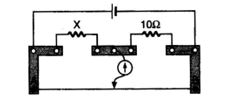
A meter bridge is set-up as shown, to determine an unknown resistance ‘X’ using a standard 10 ohm resistor. The galvanometer shows null point when tapping-key is at 52 cm mark. The end-corrections are 1 cm and 2 cm respectively for the ends A and B. The determined value of ‘X’ is:
(a) 10.2 ohm
(b) 10.6 ohm
(c) 10.8 ohm
(d) 11.1 ohm
Ans : (b)