Video Lecture

Theory For Making Notes

Terminology Used in circuit Theory


(1) Emf of cell (E) :

The potential difference across the terminals of a cell when it is not supplying any current (in open circuit) is called it’s emf (electromotive force). Remember it is not a force but it is the total work required to circulate a unit positive charge once round the circuit. Its unit is Joule/coulomb  Or volt.


(2) Potential difference (V) :

The potential difference between two points in a circuit is simply the work done in carrying a unit positive charge between those two points.Potential difference is equal to the product of current and net resistance between those two points henceV = IR.


(3) Internal resistance (r) :

In case of a cell the opposition of electrolyte to the flow of current through it is called internal resistance of the cell. A cell is said to be ideal, if it has zero internal resistance.


(4) Terminal voltage (V) :

The voltage across the terminals of a cell when it is supplying current to external resistance is called potential difference or terminal voltage. It can also be defined as the potential difference across a source(cell) when a current is passing through it i.e. in a closed circuit.


(5) Closed circuit :

Cell supplies a constant current in the circuit.

(i)

Current given by the cell I=\frac{E}{{R+r}}


(ii)

Potential difference across the resistance V=IR


(iii)

Potential drop inside the cell = Ir


(iv)

Terminal voltage of cell V=E-Ir    (E>V)


(6) Open circuit :

When no current is taken from the cell  it is said to be in open circuit

(i)   

Current through the circuit i = 0


(ii)  

Potential difference between A and B (i.e. Open ends of the circuit), VAB = E


(iii) 

Potential difference between C and D(i.e across the resistance), VCD = 0


(3) Short circuit :

If two terminals of cell are join together by a thick conducting wire of zero resistance

(i)    Maximum current (called short circuit current) flows momentarily {{i}_{{sc}}}=\frac{E}{r}


(ii)   Terminal potential or terminal voltage across the cell is zero i.e.V = 0


(i)    Maximum current (called short circuit current) flows momentarily {{i}_{{sc}}}=\frac{E}{r}

(ii)   Terminal potential or terminal voltage across the cell is zero i.e.V = 0


Series Combinations

Let the equivalent resistance between A and B equals Req , By definition, equivalent resistance is that which when connected with same battery, draw same current as drawn by the given circuit.


Hence \displaystyle {{R}_{{eq}}}=\frac{V}{I}\text{   or  }V=I.{{R}_{{eq}}}                                              . . . (1)


Now from the circuit we can write

V = IR1 + IR2 + IR3                  . . . (2)


In equation (2) put \displaystyle V=I.{{R}_{{eq}}}


We get   \displaystyle I.{{R}_{{eq}}}=I{{R}_{1}}+I{{R}_{2}}+I{{R}_{3}}


So   \displaystyle {{R}_{{eq}}}={{R}_{1}}+{{R}_{2}}+{{R}_{3}}


Important points

(i)

Same current flows through each resistance but potential difference distributes in the ratio of resistance i.e. V\propto R 


(ii)  

{{R}_{{eq}}}={{R}_{1}}+{{R}_{2}}+{{R}_{3}} equivalent resistance is greater than the maximum value of resistance in the combination.


(iii) 

If n identical resistance are connected in series then {{R}_{{eq}}}=nR and potential difference across each  resistance V’=\frac{V}{n} .


Parallel Combinations

Let the equivalent resistance between A and B equals Req , By definition, equivalent resistance is that which when connected with same battery, draw same current as drawn by the given circuit.

Hence \displaystyle {{R}_{{eq}}}=\frac{V}{I}\text{   or  I}=\frac{V}{{{{R}_{{eq}}}}}.          . . . (1)

Now from the circuit we can write

I = I1 + I2 + I3 = \displaystyle \frac{V}{{{{R}_{1}}}}+\frac{V}{{{{R}_{2}}}}+\frac{V}{{{{R}_{3}}}}      . . .  (2)


In equation (2) put \displaystyle \text{I}=\frac{V}{{{{R}_{{eq}}}}}.


So we get       \displaystyle \frac{1}{{{{R}_{{eq}}}}}=\frac{1}{{{{R}_{1}}}}+\frac{1}{{{{R}_{2}}}}+\frac{1}{{{{R}_{3}}}}


Important points

(i)

Same potential difference appeared across each resistance but current distributes in the reverse ratio of their resistance i.e. i\propto \frac{1}{R}  

(ii)

Equivalent resistance  is given by \frac{1}{{{{R}_{{eq}}}}}=\frac{1}{{{{R}_{1}}}}+\frac{1}{{{{R}_{2}}}}+\frac{1}{{{{R}_{3}}}}


Equivalent resistance is smaller than the minimum value of resistance in the combination.

(iii)         

In n identical resistance are connected in parallel

{{R}_{{eq}}}=\frac{R}{n} and current through each resistance i’=\frac{i}{n}

Method of Reduction

In this method, the series and parallel combination in a circuit are identified and then the whole circuit is reduced to a single resistor and a single cell. The current coming out of the cell is determined by using Ohm’s law and then the current distribution in each branch is done by using the following rules:

1.

When two resistors are in series each of them carry the same current.

2.

When two resistors are in parallel, the current is distributed in inverse proportion to their resistances.


  • Superposition Principle


Whenever a circuit has more than one cell or battery. The superposition principle may be used to find current and voltages. This principle is based on the fact that every cell or battery acts independent of the presence of the others.

According to this principle, the total current I in the circuit equals the algebraic sum of current I1, I2…..I4 produced by each source (cell or battery) taken one at a time


or        \displaystyle I\,\,=\,\,{{I}_{1}}\,\,+\,\,{{I}_{2}}\,\,+\,\,…….\,\,{{I}_{4}}


The superposition splits the original two-source problem into two one-source problems.

Illustration 

What is the resistance between A and B in figure.

For the two resistors are in parallel, therefore,

          \displaystyle \frac{1}{R}=\frac{1}{3}+\frac{1}{6}=\frac{2}{6}+\frac{1}{6}=\frac{3}{6}


or     R = 2Ω

This 2Ω resistor is in series with 8Ω, so

\displaystyle {{R}_{{AB}}}=2\Omega +8\Omega =10\,\Omega

Illustration

Find the equivalent resistance between the terminals A and B.

Solution

The equivalent resistance of  6Ω and 3Ω is R = \frac{{\left( 6 \right)\left( 3 \right)}}{{6+3}}=2\Omega

Using series combination

RAB= 2 + 4 + 2 = 8 Ω

Illustration

Three resistances of 12W, 16W and 20W are connected in parallel. What resistance must be connected in series with this combination to give a total resistance of 25W?

Solution

The resistance R of the parallel combination is given by

\displaystyle \frac{1}{R}=\frac{1}{{{{R}_{1}}}}+\frac{1}{{{{R}_{2}}}}+\frac{1}{{{{R}_{3}}}}=\frac{1}{{12}}+\frac{1}{{16}}+\frac{1}{{20}}=\frac{{20}}{{240}}+\frac{{15}}{{240}}+\frac{{12}}{{240}}=\frac{{47}}{{240}}


or R = 5.11Ω


Then

\displaystyle {{R}_{x}}+R=25 or \displaystyle {{R}_{x}}=25-5.11=19.89\Omega


Illustration

For the network shown in figure, find the resistance from point a to point b.

Solution

There are two parallel branches, each of resistance 3(20) = 60W.

Thus, \displaystyle 1/R=\tfrac{1}{{60}}+\tfrac{1}{{60}}+\tfrac{2}{{60}},

and \displaystyle R=30\Omega .


Illustration

In the circuit shown, the values of resistors are R= 50 Ω and R2 = 150 Ω

(a)   What are the current I, I1, and I2?

(b)   What is the total resistance of the circuit?

Solution

(a 

\displaystyle {{I}_{1}}=\frac{E}{{{{R}_{1}}}}=\frac{{12V}}{{50\Omega }}=0.24A


\displaystyle {{I}_{2}}=\frac{E}{{{{R}_{2}}}}=\frac{{12V}}{{150\Omega }}=0.08A \displaystyle I={{I}_{1}}+{{I}_{2}}=0.32A


(b)  

\displaystyle \frac{1}{R}=\frac{1}{{{{R}_{1}}}}+\frac{1}{{{{R}_{2}}}}=\frac{1}{{50\Omega }}+\frac{1}{{150\Omega }}=\frac{4}{{150\Omega }}\,\,\,R=37.5\Omega

Illustration

If the e.m.f. of the battery shown in figure is 45V and the resistor R= 300W than,

(a)   What must the resistor R2 be in order that the current I be 0.45A?

(b)   What are the currents I1 and I2?

Solution

(a)    

The total resistance must be

\displaystyle R=\frac{E}{I}=\frac{{45V}}{{0.45A}}=100\Omega

But    \displaystyle \frac{1}{R}=\frac{1}{{{{R}_{1}}}}+\frac{1}{{{{R}_{2}}}}

so     \displaystyle \frac{1}{{{{R}_{2}}}}=\frac{1}{R}-\frac{1}{{{{R}_{1}}}}=\frac{1}{{100\Omega }}-\frac{1}{{300\Omega }}=\frac{2}{{300\Omega }}

or    \displaystyle {{R}_{2}}=150\Omega

(b)         

\displaystyle {{I}_{1}}=\frac{E}{{{{R}_{1}}}}=\frac{{45V}}{{300\Omega }}=0.15A


\displaystyle {{I}_{2}}=\frac{E}{{{{R}_{2}}}}=\frac{{45V}}{{150\Omega }}=0.30A

Illustration

For the combination of resistors shown in the figure, find

(a) 

the current coming out of the battery

(b)   

the voltage drop across 3Ω resistor

Solution

(a)       

The circuit may be simplified as shown in the figure.

I1 = \displaystyle \frac{{24}}{4}=6A


I2 = \displaystyle \frac{{24}}{{12}}-=2A


I = I1 + I2 = 6 A + 2 A = 8 A


(b) 

The voltage across 3W resistor is

 V3 = 3I1 = 3(6) = 18 V


Illustration

Find I1 and I2 for the circuit of figure

 Solution

The successive reduction of the circuit is shown as follows. From figure (d),

\displaystyle {{I}_{1}}=\tfrac{6}{{12}}=0.5\text{A} .


Figure (c), \displaystyle {{V}_{{ab}}}=\left( {\tfrac{1}{2}} \right)(4)=2V .


Thus in figure (b) the drop across wire abc is 2V, and \displaystyle {{I}_{2}}=\tfrac{2}{{12}}=0.167\text{A}.

Illustration

The circuit shown below has two cells of emf 3V and 6V respectively and a resistor of 2W. We can find the current in the circuit by using superposition principle.

Solution

The given circuit may be considered as the superposition of two simple circuits as shown in figure

\displaystyle {{I}_{1}}\,\,=\,\,\frac{6}{2}\,\,\,=\,\,\,3A


\displaystyle {{I}_{2}}\,\,=\,\,\frac{3}{2}\,\,\,=\,\,\,1.5A


Since I1 and I2 are in opposite directions, therefore by using superposition principle, the net current is given by

I = I1 – I2 = 3 –1.5 = 1.5A.

Illustration

A battery of emf 10 V is connected to resistances as shown in the figure.  Determine the potential difference between A and B.

Solution:


Total resistance = \frac{{4\times 4}}{{4+4}}=2\Omega


Current I = \frac{{10V}}{{2\Omega }}=5A


Since the resistances of both the branches are equal, therefore the current of 5A shall be equally distributed.


Current through each branch = \frac{5}{2}A=2.5A


Vc – VA = 2.5 x 1 = 2.5 V


Vc – VB = 2.5 x 3 = 7.5 V.


VA – VB = (Vc – VB) – (Vc – VA) = 7.5 – 2.5 = 5.0 V.


Illustration

Find the effective resistance between the points A and B.

Solution:              

Resistors AF and FE are in series with each other. Therefore, network AEF reduces to a parallel combination of two resistors of 6Ω each. 


\displaystyle {{\text{R}}_{{\text{eq}}}}=\frac{{6\text{ }\times \text{ 6}}}{{6+6}} = 3Ω.


Similarly, the resistance between A and D is given, \displaystyle \frac{{6\text{ x 6}}}{{6+6}}= 3Ω.


Now, resistor AC is in parallel with the series combination of AD and DC. Therefore, the resistance between A and C is \displaystyle \frac{{6\text{ }\times \text{ 6}}}{{6+6}}= 3Ω.


AC + CB = 3 + 3 = 6 Ω, since they are in series


Resistance between A and B is given by,  \displaystyle \frac{1}{R}=\frac{1}{6}+\frac{1}{3}=\frac{3}{6}\text{ or }{{\text{R}}_{{\text{AB}}}}\text{ = 2}\Omega .

Internal resistance of the cell 

The opposition of electrolyte to the flow of current through it is called internal resistance of the cell.

The internal resistance of a cell depends upon

(i)   Material of the electrode

(ii)  Separation between electrodes (r\propto d)

(iii) Temperature of electrolytes \left( {r\propto \frac{1}{{temp}}} \right)

(iv) Area of electrodes \left( {r\propto \frac{1}{A}} \right)

Expression for internal resistance:

Consider a cell of emf E and internal resistance r

In open circuit, when no current is drawn from the cell, reading of voltmeter,    V=E


In closed circuit, when cell is discharging through external resistance R then voltmeter reads terminal potential difference.

Current in the circuit is given by


I=\frac{E}{{r+R}}   … (i)


and, potential difference across R


V=IR                            … (ii)


From equation (i) and (ii)


\frac{E}{{r+R}}=\frac{V}{R} ,


ER=Vr+VR


Vr=ER-VR,


r=\left( {\frac{E}{V}-1} \right)R


Combination of cells:

(i)      Series Combination:

In this combination negative terminal of each cell is connected with positive terminal of the next cell and so on.

Let,   n = no. of cell

r = internal resistance of each cell

R = external resistance

nE = total emf of the combination

nr + R = total resistance of the circuit

So, current from combination of cells,


I=\frac{{nE}}{{nr+R}}


Note: If nr = R, then current is maximum.


(ii)     Parallel combination:

Let us assume all the cells have same emf then current from combination of cells                                                    

I=\frac{E}{{\frac{r}{n}+R}}=\frac{{nE}}{{r+nR}}


(iii)    Mixed combination:

Let there be ‘m’ rows of n cells in each row


Total resistance in each row = nr


Total resistance of the circuit =\frac{{nr}}{m}+R


Total emf of the combination = nE


Net current, I=\frac{{nE}}{{\frac{{nr}}{m}+R}}=\frac{{mnE}}{{nr+mR}}


Effective grouping of cells


For effective grouping, current should be maximum

⇒           nr+mR    should be minimum. To get its minimum value we can rewrite it as given below


nr+ mR= \displaystyle {{(\sqrt{{mR}})}^{2}}+{{(\sqrt{{nr}})}^{2}}


ornr + mR =  \displaystyle {{(\sqrt{{mR}}-\sqrt{{nr}})}^{2}}+2\sqrt{{mnrR}} ,  For LHS to be minimum ,RHS should also be minimum.


As the second term can not be zero, so we conclude that the first term \displaystyle {{(\sqrt{{mR}}-\sqrt{{nr}})}^{2}} should be minimum or zero


Hence \displaystyle {{(\sqrt{{mR}}-\sqrt{{nr}})}^{2}}  = 0

⇒    mR = nr


⇒ R = \displaystyle \frac{n}{m}r


Note:When nr=mR , then current drawn from the battery is maximum.

Illustration

Find the minimum number of cells required to produce an electric current of 1.5 A through a resistance of 30 ohm. Given that the e.m.f of each cell is 1.5 volt and internal resistance of each cell is 1.0 ohm.

Solution:      

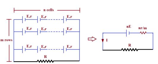
Let   (m\times n)  be the minimum number of cells arranged in m rows and each row contains n cells.

Step-1:   

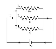
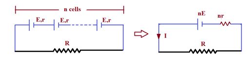
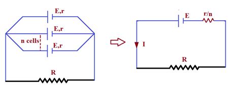
We know, Current in the mixed grouping of cells is  I=\frac{{mnE}}{{mR+nr}}


Here, I=1.5\,\,A,\,\,E=1.5\,\,V


R=30\,\,\Omega ,\,\,r=1.0\,\,\Omega


1.5=\frac{{mn\times 1.5}}{{30m+n\times 1}}


O r 45m+1.5n=1.5\,\,mn     … (i)


Step-2:   

To have maximum current


  R=\frac{{nr}}{m}        or         30=\frac{n}{m}


 or   n = 30 m                                                                … (ii)


By solving eqn. (i) and (ii), we get


n=30\times 2=60


Step 3:   

Minimum number of cells required =mn=2\times 60=120      


Illustration

Find the e.m.f and the internal resistance of a battery if the terminal potential difference is 28.5 V when giving a current of 1 A and 27 V when giving a current of 2A.

Solution:      

Step-1:   

Here V=28.5\,\,V,\,\,I=1A


V=E-Ir


\therefore \,\,\,\,\,\,\,\,\,\,E=28.5+r      … (i)


Step-2:   

Again V’=27\,\,V  and I’=2\,\,A


So,    E=27+2r                                                              …(ii)


From (i) and (ii) eqns., we get  28.5+r=27+2r


1.5=r


and   E=28.5+r =28.5+1.5


E=30\,\,volt

Practice Questions (Basic Level)

1.

What will be the equivalent resistance between the two points A and D ?      


(a)    10   

(b)    20      

(c)    30     

(d)    40

Ans.  (c)

Q.2

What is the potential difference across the points A and B ?


(a) 0.9 V                   

(b) 1.1 V                 

(c) 1.3 V                       

(d) 0.7 V

Ans.  (b)

Q.3

A parallel combination of three resistors takes a current of 7.5 A from a 30 V supply. If the two resistors are 10 \displaystyle \Omega and 12 \displaystyle \Omega , find which is the third one ?        

(a)    4 \displaystyle \Omega     

(b)    15 \displaystyle \Omega   

(c)    12 \displaystyle \Omega   

(d)    22 \displaystyle \Omega

Ans.  (b)

Q.4

In the given figure the equivalent resistance between A and B is :  

(a) 17/24 \displaystyle \Omega                    

(b) 4/3 \displaystyle \Omega                        

(c) 29 \displaystyle \Omega                          

(d) 24/17 \displaystyle \Omega

Ans. (b)

Q.5

In the figure shown, potential drop across the 3 \displaystyle \Omega resistor is :  


(a) 1 V                    

(b) 1.5V                  

(c) 2 V                    

(d) 2.5 V

Ans.   (a)

Q.6

The current flowing in the electrical circuit is 1A. If we replace all the 4 \displaystyle \Omega resistances with a 2 \displaystyle \Omega resistance, then the value of the current in the circuit will be :         


(a) 1.11 A                   

(b) 2.11 A               

(c) 3.11 A               

(d) 4.11 A

Ans.   (a)

Q.7

The potential difference across 8 ohm resistance is 48 V shown in figure. The value of potential difference across X and Y point will be :         


(a)     160 V        

(b)     128 V                

(c)      80 V         

(d)      62 V

Ans.  (a)

Q.8

A battery of e.m.f. 10 V is connected to resistances as shown in figure. The potential difference between A and B \displaystyle \left( {{{V}_{A}}-{{V}_{B}}} \right) is :  

(a)     –2V               

(b)     2 V                    

(c)     5 V                

(d)     (20/11) V

Ans.  (c)

Q.9

Calculate net resistance between A and B :     

(a)    3 \displaystyle \Omega

(b)    5 \displaystyle \Omega

(c)    6 \displaystyle \Omega

(d)    8 \displaystyle \Omega

Ans.  (b)

Q. 10

Calculate net resistance between A and B :


(a)    2 \displaystyle \Omega

(b)    3 \displaystyle \Omega

(c)    4 \displaystyle \Omega

(d)    5 \displaystyle \Omega

Ans.  (a)

Q.11

Find the equivalent resistance between the terminals A and B.

(a)        4 \displaystyle \Omega                      

(b)        8 \displaystyle \Omega                      

(c)        12 \displaystyle \Omega                    

(d)        22 \displaystyle \Omega

Ans : (b)

Q.12

Find the equivalent resistance between point and b for the combination shown in figure.


(a)     4 \displaystyle \Omega             

(b)    15 \displaystyle \Omega                       

(c)    12 \displaystyle \Omega                       

(d)     9 \displaystyle \Omega   

Ans.  (c)

Q.13

The three resistors in figure are R1 = 80 \displaystyle \Omega , R2 = 25 \displaystyle \Omega , R= 15 \displaystyle \Omega . What are the current I and I2, and the voltage across the battery, if I1 = 0.3 A?


(a)      0.9A, 0.6A           

(b)      1.9A, 1.6A

(c)      2.9A, 2.6A            

(d)      0.3A, 0.1A

Ans.  (a)

Q.14

For the circuit shown, find the current through the branch ab.

(a)       0.4 A         

(b)       1.5A            

(c)        0.5A                

(d)        1.9A

Ans.    (c)

Q.15

In the given circuit resistance of voltmeter is 400\Omega and its reading is 20V. Find the value of emf of battery

(a) 130/3 volt                                    

(b) 65 volt                                          

(c) 40 volt                                           

(d) 33.6 volt

Ans : (a)

16.

The total current supplied to the circuit by the battery is

(a)     1A             

(b)     2A

(c)     4A             

(d)     6A

Ans. (c)

Q.17

The reading of the ammeter in the figure shown is

(a) \frac{1}{8}A    

(b) \frac{3}{4}A

(c) \frac{1}{2}A    

(d) 2A

Ans.  (b)

Q.18

In the circuit shown, current through 3 \displaystyle \Omega resistance is

(a) 1 amp                            

(b) 2 amp                            

(c) 3 amp           

(d) 4 amp

Ans.  (b)

Q.19

The electric potential variation around a single closed loop containing an ideal battery and one or more resistors as shown in figure. If current of  flows in the circuit, the circuit can not have

(a)    two resistors and two batteries

(b)    one resistor and three batteries

(c)    maximum net emf of 6 volt

(d)    three resistor and one battery

Ans : (d)

Q.20

The possible circuit of close loop corresponding to the graph of previous question is

 Ans.  (iv)

Q.21

In the diagram shown, the reading of voltmeter is 20 V and that of ammeter is 4A. The value of R should be (Consider given ammeter and voltmeter are not ideal)  

(a)    Equal to 5 \displaystyle \Omega                                

(b)    Greater from 5 \displaystyle \Omega

(c)    Less than 5 \displaystyle \Omega          

(d)   Greater or less than 5 \displaystyle \Omega depends on the material of R  

Ans.  (c)

Q.22

In the circuit shown in figure, equivalent resistance between A and B is 

(a) 8 \displaystyle \Omega                                                     

(b) 15 \displaystyle \Omega

(c) \frac{3}{2} \displaystyle \Omega                                               

(d) 2 \displaystyle \Omega

Ans.  (c)

Practice Questions (JEE Main Level)

Q.1

What will be the equivalent resistance between the two points A and D ?      

(a)    10     

(b)    20      

(c)    30         

(d)    40

Ans.  (c)

Q.2

What is the potential difference across the points A and B ?

(a) 0.9 V                     

(b) 1.1 V                 

(c) 1.3 V                 

(d) 0.7 V

Ans.  (b)

Q.3

A parallel combination of three resistors takes a current of 7.5 A from a 30 V supply. If the two resistors are 10 \displaystyle \Omega and 12 \displaystyle \Omega , find which is the third one ?      


(a)    4 \displaystyle \Omega     

(b)    15 \displaystyle \Omega   

(c)    12 \displaystyle \Omega   

(d)    22 \displaystyle \Omega

Ans.  (b)

Q.4

In the given figure the equivalent resistance between A and B is :  

(a) 17/24 \displaystyle \Omega                    

(b) 4/3 \displaystyle \Omega                        

(c) 29 \displaystyle \Omega                          

(d) 24/17 \displaystyle \Omega

Ans. (b)

Q.5

In the figure shown, potential drop across the 3 \displaystyle \Omega resistor is :  

(a) 1 V                    

(b) 1.5V                  

(c) 2 V                    

(d) 2.5 V

Ans.   (a)

Q.6

The current flowing in the electrical circuit is 1A. If we replace all the 4 \displaystyle \Omega resistances with a 2 \displaystyle \Omega resistance, then the value of the current in the circuit will be :

(a)    1.11 A                   

(b) 2.11 A               

(c) 3.11 A               

(d) 4.11 A

Ans.   (a)

Q.7

The potential difference across 8 ohm resistance is 48 V shown in figure. The value of potential difference across X and Y point will be :         

(a)     160 V                         

(b)     128 V                

(c)      80 V                  

(d)      62 V

Ans.  (a)

Q.8

A battery of e.m.f. 10 V is connected to resistances as shown in figure. The potential difference between A and B \displaystyle \left( {{{V}_{A}}-{{V}_{B}}} \right) is :  

(a)     –2V                        

(b)     2 V                    

(c)     5 V                    

(d)     (20/11) V

Ans.  (c)

Q.9

Calculate net resistance between A and B :     

(a)    3 \displaystyle \Omega

(b)    5 \displaystyle \Omega

(c)    6 \displaystyle \Omega

(d)    8 \displaystyle \Omega

Ans.  (b)

Q. 10

Calculate net resistance between A and B :

(a)    2 \displaystyle \Omega

(b)    3 \displaystyle \Omega

(c)    4 \displaystyle \Omega

(d)    5 \displaystyle \Omega

Ans.  (a)

Q.11

Find the equivalent resistance between the terminals A and B.

(a)        4 \displaystyle \Omega                      

(b)        8 \displaystyle \Omega                      

(c)        12 \displaystyle \Omega                    

(d)        22 \displaystyle \Omega

Ans.   (b)

Q.12

Find the equivalent resistance between point and b for the combination shown in figure.

(a)     4 \displaystyle \Omega             

(b)    15 \displaystyle \Omega                       

(c)    12 \displaystyle \Omega                       

(d)     9 \displaystyle \Omega   

Ans.  (c)

Q.13

The three resistors in figure are R1 = 80W, R2 = 25W, R= 15W. What are the current I and I2, and the voltage across the battery, if I1 = 0.3 A?

(a)      0.9A, 0.6A           

(b)      1.9A, 1.6A

(c)      2.9A, 2.6A            

(d)      0.3A, 0.1A

Ans.  (a)

Q.14

For the circuit shown, find the current through the branch ab.

(a)       0.4 A         

(b)       1.5A            

(c)        0.5A                

(d)        1.9A

Ans.    (c)

Practice Questions (JEE Advance Level)

Q.1

In the circuit shown in figure the reading of ammeter is the same with both switches open as with both closed. Then find the resistance R. (ammeter is ideal)


Ans.  R=\frac{{150\times 100}}{{50}}=300\Omega

Q.2

By error, a student places moving-coil voltmeter V (nearly ideal) in series with the resistance in a circuit in order to read the current, as shown. The voltmeter reading will be

(a)    0               

(b)   4V                                   

(c)    6V             

(d)   12V

Ans.   (d)

Q.3

In the circuit shown, both batteries are ideal. EMF E1 of battery 1 has a fixed value, but emf E2 of battery 2 can be varied between 1 V and 10 V. The graph gives the currents through the two batteries as a function of E2, but are not marked as which plot corresponds to which battery. But for both plots, current is assumed to be negative when the direction of the current through the battery is opposite the direction of that battery’s emf. (direction of from negative to positive). The value of emf E1 is

(a)    8 V         

(b)    6 V                 

(c)   4 V           

(d)   2 V

Ans.   (b)

Q.4

In the circuit shown the variable resistance is so adjusted that the ammeter reading is same in both the position 1 and 2 of the key. The reading of ammeter is 2A. If E = 10 V, then x is

(a)    2 W 

(b)    5 W                                 

(c)   10 W                               

(d)   20 W

Ans.    (b)

Q.5

In the given circuit, the emf of the cell is 2 V and its internal resistance is negligible. The resistance of the voltmeter is 80 W. The reading of the voltmeter will be

(a)   0.8 V                              

(b)   1.6 V

(c)   1.33 V                           

(d)   2.0 V

Ans.  (c)

Q.6

Consider an infinite ladder network shown in figure. A voltage V is applied between the points A and B. This applied value of voltage is halved after each section.

(a)   R1/R2 = 1                                      

(b)   R1/R2 = 1/2                  

(c)   R1/R2 = 2                      

(d)   R1/R2 = 3

Ans. (b)

Q.7         

If the switches S1, S2 and S3 in the figure are arranged such that current through the battery is minimum, find the voltage across points A and B.            

Ans. {{V}_{{AB}}}=1\times 1=1\,V