Video Lecture
Theory For Making Notes
Mean Value of AC
Mean value of a time varying current can be found using the following equation
\displaystyle {{I}_{{av}}}=\frac{{\int{{Idt}}}}{{\int{{dt}}}} the limits of integrations depends upon the time interval in which mean value is required.
Usually the mean value of ac is calculated for two time intervals
(1) Over half time period (half cycle).
(2) Over full time period (full cycle).
The average value of ac over half cycle can be calculated as follows:
\displaystyle {{I}_{{av}}} = \displaystyle \frac{{\int\limits_{0}^{{T/2}}{{Idt}}}}{{T/2}}=\frac{{2\int\limits_{0}^{{T/2}}{{I\,dt}}}}{T} … (1)
= \displaystyle \frac{{2\int\limits_{0}^{{T/2}}{{{{I}_{0}}\sin \omega t\,(dt)}}}}{T}
= \displaystyle \frac{{2{{I}_{0}}}}{T}\left[ {-\frac{{\cos \omega t}}{\omega }} \right]_{0}^{{T/2}} = \displaystyle \frac{{2{{I}_{0}}}}{{\omega T}}\left[ {-\cos \omega \frac{T}{2}-(-\cos 0)} \right]
= \displaystyle \frac{{2{{I}_{0}}}}{{\frac{{2\pi }}{T}.T}}\left[ {-\cos \frac{{2\pi }}{T}.\frac{T}{2}+\cos 0} \right]
= \displaystyle \frac{{{{I}_{0}}}}{\pi }\left[ {-\cos \left( {\frac{{2\pi .T}}{{T.2}}} \right)-(-1)} \right]
= \displaystyle \frac{{{{I}_{0}}}}{\pi }\,\,[-\cos \pi +1]
(ii) Similarly for calculating mean value of alternating current over full cycle we have to replace the limit of integration in equation (1) by 0 to T. Solving integration in the same way we find that the mean value of ac over full cycle is zero. Also looking at graph, the positive current pattern is equal and opposite to negative pattern, hence mean value of ac over full cycle is zero.
RMS value
The rms value of any quantity is “square root of the arithmetic mean of squares of all those values whose rms value is required”. RMS value is also called effective values.
Thus rms value of 1, 2, 3, 4 is
\displaystyle \sqrt{{({{1}^{2}}+{{2}^{2}}+{{3}^{2}}+{{4}^{2}})/4}} \displaystyle =\sqrt{{\frac{{15}}{2}}}
RMS value of AC
In case of AC, the rms value of an AC comes out to be that value of DC which will produce the same heating effect on passing through the same resistance over the same period of time. Hence rms value of ac is also called Equivalent DC ( \displaystyle {{I}_{{eq}}})
If the magnitude (I) of AC at any instant of time is given by
\displaystyle I\text{ }=\text{ }{{I}_{0}}sin\omega t,
Then heat (H) produced by this AC when passed through a resistance (R) during one time period (T) will given by
\displaystyle H=\int\limits_{0}^{T}{{dH}}=\int\limits_{0}^{T}{{{{I}^{2}}\,Rdt}} … (i)
And during this one time period T, the heat produced by a DC ( \displaystyle {{I}_{{rms}}} or \displaystyle {{I}_{{eq}}}) will be
H \displaystyle =I_{{rms}}^{2}RT … (ii)
Hence, equation (i) and (ii), when equated will give us the value of the equivalent DC or rms value of ac ( \displaystyle {{I}_{{eq}}}).
\displaystyle I_{{rms}}^{2}RT = \displaystyle \int\limits_{0}^{T}{{{{I}^{2}}Rdt}}=\int\limits_{0}^{T}{{{{{({{I}_{0}}\sin \omega t)}}^{2}}R\,\,dt}}
= \displaystyle I_{0}^{2}R\int\limits_{0}^{T}{{{{{\sin }}^{2}}\omega t\,\,dt}}
= \displaystyle I_{0}^{2}R\,\,\int\limits_{0}^{T}{{\left( {\frac{{1-\cos 2\omega t}}{2}} \right)}}\,\,dt [because \displaystyle \text{cos(2 }\!\!\omega\!\!\text{ t)= 1 — 2 si}{{\text{n}}^{\text{2}}}\text{ }\!\!\omega\!\!\text{ t})
= \displaystyle \frac{{I_{0}^{2}R}}{2}\left[ {\int\limits_{0}^{T}{{dt}}-\int\limits_{0}^{T}{{\cos \,2\omega t\,\,dt}}} \right]
= \displaystyle \frac{{I_{0}^{2}R}}{2}\left[ {T-\left\{ {\frac{{\sin 2\omega t}}{{2\omega }}} \right\}_{0}^{T}} \right]
\displaystyle =\frac{{I_{0}^{2}RT}}{2}
[Because when \displaystyle \text{t = T, sin2 }\!\!\omega\!\!\text{ t = sin 2 }\!\!\omega\!\!\text{ T = sin(2}\text{. (2 }\!\!\pi\!\!\text{ /T) }\!\!\times\!\!\text{ T)} \displaystyle =\text{ }sin\text{ }4\pi =\text{ }0;\text{ }and\text{ }also\text{ }at\text{ t}=\text{ }0,\text{ }sin\text{ }2\omega t=\text{ }sin\text{ }0\text{ }=\text{ }0].
hence \displaystyle I_{{rms}}^{2}RT=\frac{{I_{0}^{2}RT}}{2} or \displaystyle I_{{rms}}^{2}=\frac{{I_{0}^{2}}}{2}
or \displaystyle I_{{rms}}^{{}}=\frac{{{{I}_{0}}}}{{\sqrt{2}}} Similarly \displaystyle {{E}_{{rms}}}=\frac{{{{E}_{0}}}}{{\sqrt{2}}}
Illustration
The electric current in a circuit is given \displaystyle i={{i}_{o}}\frac{t}{\tau}for some time. Calculate the rms current for the period t = 0 to \displaystyle t\text{ }=\tau .
Solution
\displaystyle {{I}_{{rms}}}=\sqrt{{\frac{{\int\limits_{0}^{\tau }{{{{I}^{2}}.dt}}}}{{\int\limits_{0}^{\tau }{{dt}}}}}}=\,\,\sqrt{{\frac{{\int\limits_{0}^{\tau }{{\frac{{I_{0}^{2}\,\,{{t}^{2}}}}{{{{\tau }^{2}}}}\,\,.\,\,dt}}}}{\tau }}}
\displaystyle =\sqrt{{\frac{{I_{0}^{2}}}{{{{\tau }^{3}}}}\left[ {\frac{{{{t}^{3}}}}{3}} \right]_{0}^{\tau }}}=\sqrt{{\frac{{I_{0}^{2}}}{{{{\tau }^{3}}}}.\frac{{{{\tau }^{3}}}}{3}}}-0 = \displaystyle \frac{{{{I}_{0}}}}{{\sqrt{3}}} Ans.
Simple AC Circuits
AC circuit containing only a Resistor
Figure shows a circuit containing an AC source \displaystyle E\text{ }=\text{ }{{E}_{o}}sin\omega t and a resistor of a resistance R.
Such a circuit is also known as a purely resistive circuit.
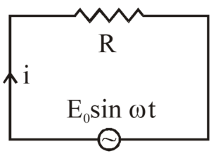
If the current at time t is I(t), Kirchhoff’s loop law gives \displaystyle I(t).R=\text{ }{{E}_{o}}sin\omega t
or, \displaystyle I(t)=\frac{{{{E}_{0}}}}{R}\sin \omega t
\displaystyle I(t)=\text{ }{{\text{I}}_{o}}sin\omega t
where \displaystyle {{I}_{0}}=\frac{{{{E}_{0}}}}{R}
Phasor Diagram
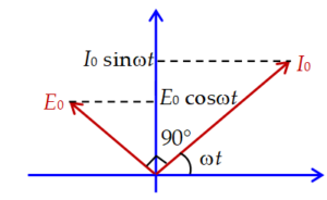
A diagram representing alternating voltage and current as rotating vectors with angular velocity \displaystyle \omega in the counter clockwise direction.
In these diagram the instantaneous value of a quantity that varies sinusoidally with time is represented by the projection onto a vertical axis (if it is a sine function) or onto a horizontal axis (if it is a cosine function) of a vector with a length equal to the amplitude ( \displaystyle {{I}_{0}}) of the quantity. The vector rotates counter clockwise with constant angular velocity \displaystyle \omega .
As in case of a pure resistor current and voltages are in same phase hence on phasor diagram the peak value or rms value of voltage and current can be shown by two collinear vectors as given below
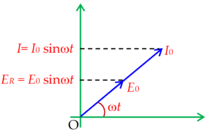
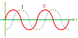
Graphically the current and emf can be shown by two waves which reach zero and peak value at the same time.

Average Power
The mean value of power over one complete cycle can be found as given below:
\displaystyle {{P}_{{av}}}=\frac{{\int\limits_{0}^{T}{{P.dt}}}}{T}=\frac{{\int\limits_{0}^{T}{{E.I.dt}}}}{T}
Putting source \displaystyle E\text{ }=\text{ }{{E}_{o}}sin\omega t and \displaystyle I=\text{ }{{\text{I}}_{o}}sin\omega t in the above equation and solving we get
\displaystyle {{P}_{{avg}}}~=\text{ }{{E}_{{rms}}}~.\text{ }{{I}_{{rms}}}
Circuit containing only an inductor
Figure shows an inductor connected to an AC source. Such a circuit also known as a purely inductive circuit.
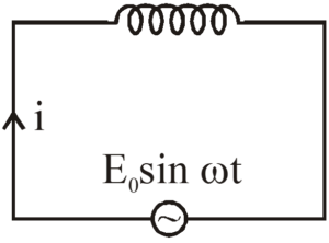
The induced emf across the inductor is \displaystyle -L\frac{{dI}}{{dt}} so from Kirchhoff’s loop law,
\displaystyle {{E}_{0}}\sin \omega t-L\frac{{dI}}{{dt}}=0 or, \displaystyle \frac{{dI}}{{dt}}=\frac{{{{E}_{0}}}}{L}\sin \omega t integrating the equation \displaystyle I=-\frac{{{{E}_{0}}}}{{\omega L}}\cos \omega t or, \displaystyle I=\frac{{{{E}_{0}}}}{{\omega L}}\sin (\omega t-\pi /2)
|
or, \displaystyle I={{I}_{0}}\sin (\omega t-\pi /2)
where as \displaystyle E\text{ }=\text{ }{{E}_{o}}sin\omega t … (3)
where \displaystyle {{I}_{0}}=\frac{{{{E}_{0}}}}{{\omega L}}
The term \displaystyle \omegaL plays the role of effective resistance in this circuit and is denoted by \displaystyle {{X}_{L}}. It is called the inductive reactance of the inductor. The graph between \displaystyle {{X}_{L}} and \displaystyle \nu is shown below
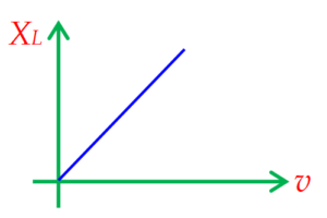
It is zero for direct current (as \displaystyle \omega = 0) and increases as the frequency is increased.
We see from equation number (2) and (3) that the phase of the current is \displaystyle \frac{\pi }{2} less than that of the emf. The current lags behind the emf by \displaystyle \frac{\pi }{2} (radians).
Figure shows plots of the current through an inductor and of the emf as time passes
The above relation of phase angle between current and emf can be represented on a phasor diagram by drawing peak current and peak emf as two mutually perpendicular vectors as shown below:
Average power over full cycle:
As \displaystyle {{P}_{{av}}}=\frac{{\int\limits_{0}^{T}{{P.dt}}}}{T}=\frac{{\int\limits_{0}^{T}{{E.Idt}}}}{T}
Substituting \displaystyle E\text{ }=\text{ }{{E}_{o}}sin\omega t and \displaystyle \text{I = }{{\text{I}}_{\text{o}}}\text{ }\!\!~\!\!\text{ sin ( }\!\!\omega\!\!\text{ t — }\!\!\pi\!\!\text{ /2)}in the above equation and solving we get
\displaystyle {{P}_{{av}}}~=\text{ }0
Practice Questions (Basic Level)
Q.1
The reactance of a 25 µF capacitor at the AC frequency of 4000 Hz is
(a) \displaystyle \frac{5}{\pi }\Omega
(b) \displaystyle \sqrt{{\frac{5}{\pi }}}\Omega
(c) \displaystyle 10\,\Omega
(d) \displaystyle \sqrt{{10}}\,\Omega
Ans. (a)
Q.2
What will be the approximate resistance offered by a capacitor of 10 µF and frequency 100 Hz ?
(a) 160 Ω (b) 1600 Ω (c) 16 Ω (d) None of the above
Ans. (a)
Q.3
An AC voltage is applied to a resistance R and an inductor L in series. If R and the inductive reactance are both equal to 3Ω, the phase difference between the applied voltage and the current in the circuit is
(a) π / 4 (b) π / 2 (c) zero (d) π / 6
Ans. (a)
Q.4
The power factor of an R–L circuit is \displaystyle \frac{1}{{\sqrt{2}}}. If the frequency of AC is doubled, what will be the power factor ?
(a) \displaystyle \frac{1}{{\sqrt{3}}}
(b) \displaystyle \frac{1}{{\sqrt{5}}}
(c) \displaystyle \frac{1}{{\sqrt{7}}}
(d) \displaystyle \frac{1}{{\sqrt{{11}}}}
Ans. (b)
Q.5
An inductive coil has a resistance of 100 Ω. When an AC signal of frequency 1000 Hz is applied to the coil, the voltage leads the current by 45º. The inductance of the coil is
(a) \displaystyle \frac{1}{{10\pi }}
(b) \displaystyle \frac{1}{{20\pi }}
(c) \displaystyle \frac{1}{{40\pi }}
(d) \displaystyle \frac{1}{{60\pi }}
Ans. (b)
Q.6
Two coils have a mutual inductance 0.005 H. The current changes in the first coil according to equation \displaystyle I={{I}_{0}}\,\sin \,\omega t, where \displaystyle {{I}_{0}}=10A and \displaystyle \omega =100\pi \,rad/s. The maximum value of emf in the second coil is (in volt).
(a) 2 \displaystyle \pi
(b) 5 \displaystyle \pi
(c) \displaystyle \pi
(d) 4 \displaystyle \pi
Ans. (b)
Q.7
In an AC circuit, V and I are given by V = 150 sin (150 t) volt and \displaystyle I=150\sin \left( {150\,t+\frac{\pi }{3}} \right) The power dissipated in the circuit is
(a) 106 W (b) 150 W (c) 5625 W (d) zero
Ans. (c)
Q.8
In an AC circuit an alternating voltage \displaystyle e=200\sqrt{2}\sin 100\,tvolt is connected to a capacitor of capacity 1µF. The rms value of the current in the circuit is
(a) 100 mA (b) 200 mA (c) 20 mA (d) 10 mA
Ans. (c)
Q.9
An AC voltage is applied to a resistance R and an inductor L in series. If R and the inductive reactance are both equal to 3Ω, the phase difference between the applied voltage and the current in the circuit is
(a) π/4 (b) π/2 (c) zero (d) π/6
Ans. (a)
Q.10
In the case of an inductor
(a) voltage lags the current by \displaystyle \frac{\pi }{2}
(b) voltage leads the current by \displaystyle \frac{\pi }{2}
(c) voltage leads the current by \displaystyle \frac{\pi }{3}
(d) voltage leads the current by \displaystyle \frac{\pi }{4}
Ans. (b)
Q.11
The inductive time constant in an electrical circuit is
(a) \displaystyle L\,R
(b) \displaystyle \frac{L}{R}
(c) \displaystyle \sqrt{{\frac{L}{R}}}
(d) \displaystyle \frac{R}{L}
Ans. (b)
Q.12
In an AC circuit, V and i are given by V = 100 sin (100 t) volt and \displaystyle i=100\sin \left( {100\,t+\frac{\pi }{3}} \right)amp The power dissipated in the circuit is
(a) 104 W (b) 2.5 kW (c) 5 kW (d) 5 W
Ans. (b)
Q.13
The reactance of 25 µF capacitor at the AC frequency of 4000 Hz is
(a) \displaystyle \frac{5}{\pi }Ω
(b) \displaystyle \sqrt{{\frac{5}{\pi }}}Ω
(c) 10 Ω
(d) \displaystyle \sqrt{{10}}Ω
Ans. (a)
Q.14
The frequency for which a 5 µF capacitor has a reactance of \displaystyle \frac{1}{{1000}}Ω is given by
(a) \displaystyle \frac{{100}}{\pi }MHz
(b) \displaystyle \frac{{1000}}{\pi }Hz
(c) \displaystyle \frac{1}{{1000}}Hz
(d) 1000 Hz
Ans. (a)
Q.15
The capacity of a pure capacitor is 1 F. In DC circuits, its effective resistance will be
(a) zero (b) infinite (c) 1 Ω (d) 1/2 Ω
Ans. (b)
Q.16
The rms voltage of the wave form shown is
(a) 10 V
(b) 7 V
(c) 6.37 V
(d) None of these
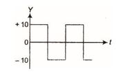
Ans. (a)
Q.17
The output sinusoidal current versus time curve of a rectifier is shown in the figure. The average value of output current in this case is
(a) 0
(b) \displaystyle \frac{{{{I}_{0}}}}{2}
(c) \displaystyle \frac{{2{{I}_{0}}}}{\pi }
(d) \displaystyle {{I}_{0}}
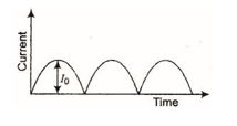
Ans. (c)
18.
The capacitor reactance of a capacitor in d.c. circuit in ohms is
(A) \frac{1}{{\omega C}}
(B) \displaystyle \omega C
(C) zero
(D) \displaystyle \infty
Ans (A)
19.
The reactance of a inductor at 50 Hz is 10 \displaystyle \Omega . What will be its reactance at 200 Hz ?
(A) 10 \displaystyle \Omega
(B) 40 \displaystyle \Omega
(C) 2.5 \displaystyle \Omega
(D) 20 \displaystyle \Omega
Ans (B)
20.
An inductive circuit contains a resistance of 10 \displaystyle \Omega and inductance of 2H. If an a.c. voltage of 120 V and frequency 60 Hz is applied to this circuit, the current in circuit would be nearly
(A) 0.32 A
(B) 0.16 A
(C) 0.48 A
(D) 0.80 A
Ans (B)
21.
What is the average value of a.c. over a half cycle
(A) zero
(B) \frac{{{{I}_{0}}}}{\pi }
(C) \displaystyle \frac{{2{{I}_{0}}}}{\pi }
(D) none of these
Ans (C)
22.
In an AC circuit having R and L in serries
(A) voltage leads current
(B) current leads voltage
(C) voltage and current are increase
(D) voltage and current are in opposite phase
Ans (A)
23.
Average power in a pure inductive circuit is
(A) irms´ vrms
(B) 2 irms´ vrms
(C) 1
(D) zero
Ans (D)
24.
The root mean square value of voltage (V) in an AC circuit is
(A) 0.637Vmax
(B) 0.707 Vmax
(C) 2Vmax
(D) \sqrt{2}Vmax
Ans (B)
25.
In an AC series circuit, instantaneous voltage is maximum while instantaneous current is zero. The source is connected to
(A) pure inductor only
(B) pure resistance only
(C) pure capacitor only
(D) (A) or (C)
Ans (D)
26.
In the circuit shown, the voltage in C & L are
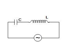
(A) out of phase by \displaystyle \pi
(B) out of phase by \displaystyle \pi /2
(C) out of phase by \displaystyle \pi /4
(D) In Phase
Ans (A)
27.
If the mean value of an alternating voltage is \frac{{28\sqrt{2}}}{\pi } volt, its rms value is
(A) 28 volt
(B) 14 volt
(C) 14 \sqrt{2} volt
(D)zero
Ans (B)
28.
When an alternating voltage source is connected to a pure inductor, the difference between phase of instantaneous current through the inductor and the phase of instantaneous potential difference across the inductor at t = T/4 sec. is
(A)zero
(B) \displaystyle \pi /2 rad.
(C) – \displaystyle \pi /2 rad.
(D) \displaystyle \pi /4 rad.
Ans (C)
Practice Questions (JEE Main Level)
1.
An alternating current is given by i = i1 cos \displaystyle \omega t + i2 sin \displaystyle \omega t. The rms current is given by
(A) i1 + i2
(B) ( \sqrt{{{{i}_{1}}}}+\sqrt{{{{i}_{2}}}})2
(C) \frac{{{{i}_{1}}+{{i}_{2}}}}{2}
(D) none of the above
Ans (D)
2.
The current in a series RL circuit decays as I={{I}_{0}}{{e}^{{-t/\tau }}}. Obtain the rms current in the interval 0\le t\le \tau .
(a) \frac{{{{I}_{0}}}}{2}
(b) \frac{{{{I}_{0}}}}{e}
(c) \frac{{{{I}_{0}}}}{{\sqrt{2}e}}
(d) \frac{{{{I}_{0}}}}{e}\sqrt{{\frac{{{{e}^{2}}-1}}{2}}}
Ans (d)
3.
An alternating voltage is given by e={{e}_{1}}\sin \omega t+{{e}_{2}}\cos \omega t. Then, the root mean square value of voltage is given by
(a) \sqrt{{e_{1}^{2}+e_{2}^{2}}}
(b) \sqrt{{{{e}_{1}}+{{e}_{2}}}}
(c) \sqrt{{\frac{{{{e}_{1}}{{e}_{2}}}}{2}}}
(d) \sqrt{{\frac{{e_{1}^{2}+e_{2}^{2}}}{2}}}
Ans (d)
Practice Questions (JEE Advance Level)
1.
In an inductor of self-inductance L = 2mH, current changes with time according to relation I={{t}^{2}}{{e}^{{-t}}}.At what time e.m.f. is zero?
(a) 4 s
(b) 3 s
(c) 2 s
(d) 1 s
Ans (c)