Video Lecture
Theory For Notes Making
Capacitor
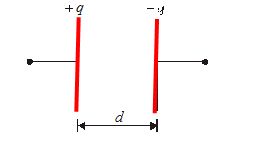
The capacitor is a device that store electrical energy. In its most common form, it is an arrangement of two conductors (usually of same shape), carrying charges of equal magnitude but of opposite sign, separated by an insulating medium.
The capacitance of a capacitor is defined as
\mathbf{C}=\frac{{\mathbf{Magnitude}\,\,\mathbf{of}\,\mathbf{charge}\,\,\mathbf{on}\,\,\mathbf{inner}\,\mathbf{plate}}}{{\mathbf{PD}\,\,\mathbf{between}\,\,\mathbf{the}\,\,\mathbf{plates}}} = \frac{q}{V}
It is a scalar quantity . The dimensions of capacitance can be found from the formula C=\frac{q}{V} having dimensions.
\because \,\,\,\,\,C=\frac{q}{V}=[{{M}^{{-1}}}{{L}^{{-2}}}{{T}^{4}}{{A}^{2}}]
Its SI unit is coulomb/volt and is called Farad (F) and practical units are micro farad (\mu F) or picofarad (pF)
⇒ 1\,\,\mu F={{10}^{{-6}}}F
⇒ 1\,\,pF={{10}^{{-12}}}F
Types of capacitors on the bases of the shape of the conductors used
Parallel plate Capacitor
Capacitance of the Parallel plate capacitor with air as an insulator
A parallel plate capacitor consists of two equal flat parallel metal plates facing each other and separated by distance d.
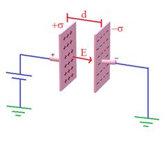
Net electric field between plates, E=\frac{\sigma }{{2{{\varepsilon }_{o}}}}-\frac{{(-\sigma )}}{{2{{\varepsilon }_{o}}}}=\frac{\sigma }{{{{\varepsilon }_{o}}}}
( \sigma =\frac{q}{A} is the surface charge density of the plates)
Since E=\frac{V}{d}=\frac{q}{{A{{\varepsilon }_{o}}}} , so V=\frac{{qd}}{{A{{\varepsilon }_{o}}}}
C=\frac{q}{V}=\frac{{A{{\varepsilon }_{o}}}}{d}
The capacitance of the capacitor filled with medium of dielectric constant K is C=\frac{{K{{\varepsilon }_{0}}A}}{d}
Parallel plate capacitors with unequal plates
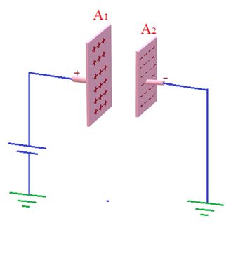
If plates are of unequal size, then
C=\frac{{{{A}_{2}}{{\varepsilon }_{0}}}}{d}
where {{A}_{2}} is the area of smaller plate.
Capacity of spherical conductor
While calculating the capacitance of a single sphere we consider the other sphere of infinite size.
The potential at surface of the spherical conductor is V=\frac{1}{{4\pi {{\varepsilon }_{o}}}}\frac{Q}{R}
Since C=\frac{Q}{V} , so C=\frac{Q}{V}
If we assume the earth to be a conductor then its capacity will be
C=4\pi {{\varepsilon }_{0}}R
C=711\,\,\mu F
(\because \,\,\,R=6400\,\,km)
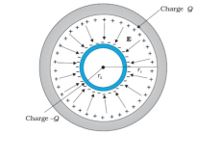
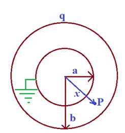
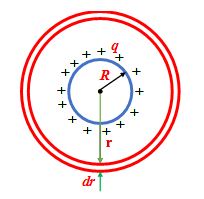
Capacitance of Concentric spherical shells
Case- I: When the outer sphere is earthed or taken at zero potential
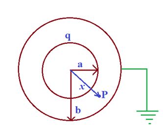
Let a charge ‘q’ is given to the inner shell of radius ‘a’ and outer shell of radius ‘b’ is earthed.
Let induced charge is q’ at B.
Now potential at B is given as
{{V}_{B}}=\frac{{kq}}{b}+\frac{{kq’}}{b} \left( {k=\frac{1}{{4\pi {{\varepsilon }_{0}}}}} \right)
Now ‘B’ is earthed, so {{V}_{B}}=0
q’=-q
So shell behaves as spherical capacitor. Now take any point ‘P’ at a distance ‘x’ from center. Electric field at P is given by
E=K\frac{q}{{{{x}^{2}}}}=-\frac{{dV}}{{dx}}\text{ or }dV=-Edx
Integrating \int\limits_{V}^{0}{{dV}}=-\int\limits_{a}^{b}{{\frac{{KV}}{{{{x}^{2}}}}dx}}
\Rightarrow \text{ }[0-V]=+Kq\left[ {\frac{1}{x}} \right]_{a}^{b}
\Rightarrow \text{ }-V=Kq\left[ {\frac{1}{b}-\frac{1}{a}} \right]\text{ or V=}Kq\left[ {\frac{1}{a}-\frac{1}{b}} \right]
\Rightarrow \text{ }-V=Kq\left[ {\frac{1}{b}-\frac{1}{a}} \right]\text{ or V=}Kq\left[ {\frac{1}{a}-\frac{1}{b}} \right]
C=\frac{{4\pi {{\varepsilon }_{0}}ab}}{{(b-a)}}
Case- II: When the inner sphere is earthed or taken at zero potential
If charge ‘q’ is given to B and inner is earthed. Consider induced charge is in A.
{{V}_{A}}=K\frac{q}{b}+K\frac{{q’}}{a}=0 ( A is earthed)
q’=-\frac{a}{b}q
Now shell will not behave as a capacitor as the summation of charges on interior of surfaces is not equal to zero.
Let P is point at ‘x’ distance from center
E=\frac{{Kq’}}{{{{x}^{2}}}}=-\frac{{dV}}{{dx}}\text{ or }dV=-Edx
hence dV=-\frac{{Kq}}{{{{x}^{2}}}}dx
integrating \int\limits_{0}^{V}{{dV=Kq\frac{a}{b}}}\int\limits_{a}^{b}{{\frac{{dx}}{{{{x}^{2}}}}}}
\Rightarrow \text{ }V-0=K\frac{{qa}}{b}\left[ {\frac{1}{a}-\frac{1}{b}} \right]
\Rightarrow \text{ }V=K\frac{{q(b-a)}}{{{{b}^{2}}}}
C=\frac{q}{V}=\frac{{4\pi {{\varepsilon }_{0}}{{b}^{2}}}}{{(b-a)}}
Cylindrical Capacitor
It consists of two coaxial cylinder. The inner cylinder is a thin cylinder and acts like a line of charge surrounded by a cylindrical shell.
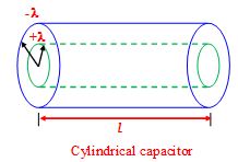
Hence in the space between the two cylinders the electric field is given by
E = \frac{\lambda }{{2\pi {{\varepsilon }_{o}}r}} a£r £b
The potential difference between them can be calculated as follows
V = Va–Vb= – \int\limits_{b}^{a}{{E\,dr}}
or V = \frac{\lambda }{{2\pi {{\varepsilon }_{o}}}}\,\ln \,\,\left| {\frac{b}{a}} \right|
\therefore \text{ C=}\frac{q}{V}\,=\frac{{\lambda \,l}}{V}\,=\frac{{2\pi {{\varepsilon }_{o}}l}}{{\ln \,\left| {\frac{b}{a}} \right|}}
Combination of Capacitors
(A) Series Combination
The figure shows three capacitors connected in series as shown in the figure. In this case, the magnitude of charge q on each plate must be zero. This is so because the battery produces charges on two plates to which it is connected. It transfers charge from leftmost plate to the rightmost plate and maintains a potential difference V between them. Charges that are produced on other plates are merely due to shifting of charge between them and net charge on them still remain zero. For instance, the part of the circuit enclosed by the dashed lines is electrically isolated from rest of the circuit and connection to a battery merely produces a charge separation.
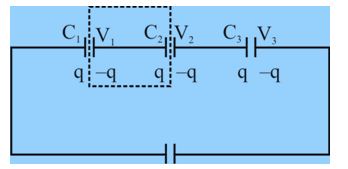
To derive an expression for Ceq , we apply the relation q = CV to each of the capacitor.
\displaystyle {{V}_{1}}=\frac{q}{{{{c}_{1}}}},{{V}_{2}}=\frac{q}{{{{c}_{2}}}},{{V}_{3}}=\frac{q}{{{{c}_{3}}}}
The Total Potential Difference of The Series Combination is The Sum Of These Three Potential Differences
\displaystyle V={{V}_{1}}+{{V}_{2}}+{{V}_{3}}=q\left[ {\frac{1}{{{{c}_{1}}}}+\frac{1}{{{{c}_{2}}}}+\frac{1}{{{{c}_{3}}}}} \right]
The equivalent capacitance
\displaystyle C=\frac{q}{V}=\frac{1}{{1/{{C}_{1}}+1/{{C}_{2}}+1/{{C}_{3}}}}
\displaystyle \frac{1}{{{{C}_{{eqv}}}}}=\frac{1}{{{{C}_{1}}}}+\frac{1}{{{{C}_{2}}}}+\frac{1}{{{{C}_{3}}}}
This result can easily be extended to n capacitors in series as
\displaystyle \frac{1}{{{{C}_{{eqv}}}}}=\sum\limits_{{i=1}}^{n}{{\frac{1}{{{{C}_{i}}}}}}
Please note that Ceq is always less that smallest capacitance in the chain.
Note : Capacitors are said to be in series if charge on each individual capacitor is same, i.e. q={{q}_{1}}={{q}_{2}}={{q}_{3}} (provided initially all capacitors are uncharged).Actually in series circuit the charge flowing is same in the entire circuit.
In series as q is same for all capacitors and as q=CV potential divides in the inverse ratio of capacities i.e.,
{{V}_{1}}:{{V}_{2}}:{{V}_{3}}::\frac{1}{{{{C}_{1}}}}:\frac{1}{{{{C}_{2}}}}:\frac{1}{{{{C}_{3}}}}
If n plates are arranged in series (n – 1) capacitors constitute in series and each of value \frac{{{{\varepsilon }_{0}}A}}{d} ,
so that {{C}_{R}}=\frac{{{{\varepsilon }_{0}}A}}{{d(n-1)}}
Parallel Combination
Figure shows three capacitors connected in parallel. In this case potential difference across each of the capacitors is same. This is true because all the upper plates are connected to the positive terminal and all the lower plates are connected to the negative terminal of the battery.
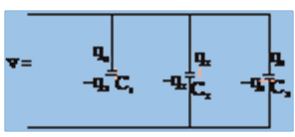
Applying the relation q = CV to each capacitor leads to
\displaystyle {{q}_{1}}={{C}_{1}}V,{{q}_{2}}={{C}_{2}}V,{{q}_{3}}={{C}_{3}}V
The total charge on the parallel combination is
\displaystyle q={{q}_{1}}+{{q}_{2}}+{{q}_{3}}=({{C}_{1}}+{{C}_{2}}+{{C}_{3}})V
The equivalent capacitance on Ceq with the total charge q and applied potential difference V, is then
\displaystyle {{C}_{{eq}}}=\frac{q}{V}={{C}_{1}}+{{C}_{2}}+{{C}_{3}}
This result can easily be extended to n capacitors in parallel as
\displaystyle {{C}_{{eq}}}=\sum\limits_{{i=1}}^{n}{{{{C}_{i}}}}
Note In parallel as V is same for all capacitors and as q=Cv, charge divides in proportion to capacities i.e., {{q}_{1}}:{{q}_{2}}:{{q}_{3}}\,\,\,\,\,::{{C}_{1}}:{{C}_{2}}:{{C}_{3}}
In parallel n plates arranged so that {{C}_{R}}=(n-1)\frac{{{{\varepsilon }_{0}}A}}{d}
Energy stored in a Capacitor
The energy stored in a capacitor is equal to the work done to charge it. Let q be the instantaneous charge on either plate of the capacitor and the potential difference between the plates is V = \frac{q}{C} . The work done to transfer an infinitesimal charge dq from the negative plate to the positive plate is
dW = Vdq = \left( {\frac{q}{C}} \right)\,dq
The charge moves through the wires, not across the gap between the plates.
The total work done to transfer charge Q is
W = \displaystyle \int\limits_{0}^{Q}{{\frac{q}{C}\,dq\,=\frac{{{{Q}^{2}}}}{{2C}}\,=\frac{{QV}}{2}\,=\frac{1}{2}\,C{{V}^{2}}}}
Since the charge on each plate is unaffected the capacitance in the presence of the dielectric is
C = \frac{{{{q}_{0}}}}{A}\,=\frac{{k{{q}_{o}}}}{{{{V}_{o}}}}\,=\,k{{C}_{o}}
The capacitance of the capacitor increases by a factor k.
Where is the Potential Energy stored ?
The energy is stored in the space occupied by the electric field. In the case of parallel plate capacitor electric field is confined in the spacing between the plates.
C = \frac{{{{\varepsilon }_{o}}A}}{d}
and V = Ed
U = \frac{1}{2} CV2 = \frac{1}{2} \left( {\frac{{{{\varepsilon }_{0}}A}}{d}} \right) (Ed)2 = \frac{1}{2} eoE2 (Ad)
Since volume between the plates where the field exists is Ad, the energy densityor the energy per unit volume is
u = \displaystyle \frac{\text{U}}{{Ad}}\,=\frac{1}{2}\,{{\varepsilon }_{o}}{{E}^{2}}
FORCE BETWEEN THE PLATES OF PARALLEL PLATE CAPACITOR:
In a capacitor, as plates carry equal and opposite charges, there is force of attraction between the plates.
We know that the electric field is conservative and in a conservative field, F=-\frac{{dU}}{{dx}}
In case of a parallel plate capacitor, U=\frac{{{{q}^{2}}}}{{2C}}
\displaystyle \left| F \right|=\frac{1}{2}qE
Putting C=\frac{{{{\varepsilon }_{o}}A}}{x} where x is the distance between two plates we get \displaystyle U=\frac{{{{q}^{2}}x}}{{2A{{\varepsilon }_{o}}}}
Now \displaystyle F=-\frac{{dU}}{{dx}}=-\frac{d}{{dx}}\left[ {\frac{{{{q}^{2}}x}}{{2{{\varepsilon }_{o}}A}}} \right]
\displaystyle \Rightarrow \text{ }F=-\frac{{{{q}^{2}}}}{{2{{\varepsilon }_{o}}A}} ——(1)
Force per unit area
\displaystyle \Rightarrow \text{ }\frac{F}{A}=-\frac{{{{q}^{2}}}}{{2{{\varepsilon }_{o}}{{A}^{2}}}}=-\frac{{{{\sigma }^{2}}}}{{2{{\varepsilon }_{o}}}}
\displaystyle \therefore \text{ }\left| {\frac{F}{A}} \right|=\frac{{{{\sigma }^{2}}}}{{2{{\varepsilon }_{o}}}}
Each of plate of capacitor is placed in field of other plate
The electric field of a single plate is \displaystyle \text{E}=\frac{{{{\sigma }^{{}}}}}{{2{{\varepsilon }_{o}}}}=\frac{{{{q}^{{}}}}}{{2A{{\varepsilon }_{o}}}}
Force acting on negative plate is = -qE =-q\frac{q}{{2A{{\varepsilon }_{0}}}} = \displaystyle -\frac{{{{q}^{2}}}}{{2A{{\varepsilon }_{o}}}}
Or \displaystyle \left| F \right|=\frac{1}{2}qE
–ve sign indicates that nature of force is attractive.
Illustration
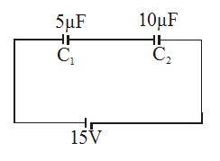
Calculate the Charge on each capacitor shown in the figure.
Solution
Since the two capacitors are joined in series, their equivalent capacitance is given by
\displaystyle \frac{1}{{{{C}_{{eq}}}}}=\frac{1}{{{{C}_{1}}}}+\frac{1}{{{{C}_{2}}}}
\displaystyle {{C}_{{eq}}}=\frac{{{{C}_{1}}{{C}_{2}}}}{{{{C}_{1}}+{{C}_{2}}}}=\frac{{5\times 10}}{{15}}=\frac{{10}}{3}\mu F
The charge on each of the capacitors is
\displaystyle Q={{C}_{{eq}}}V=\left( {\frac{{10}}{3}\mu F} \right)(75V)=50\mu C
Illustration
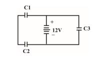
In the figure shown
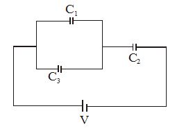
\displaystyle {{C}_{1}}=10\mu F,{{C}_{2}}=5\mu F,{{C}_{3}}=5\mu F
(a) Find the equivalent capacitance for the combination of capacitance shown in the figure.
(b) If the potential difference V = 10V, what is the charge on C1?
Solution
(a)
Here C1 and C2 are in parallel, so their equivalent capacitance is
\displaystyle {{C}_{{12}}}={{C}_{1}}+{{C}_{2}}=10+5=15\mu F
The combination of C1 and C2 is in series with C3. Therefore
\displaystyle \frac{1}{{{{C}_{{eq}}}}}=\frac{1}{{{{C}_{{12}}}}}+\frac{1}{{{{C}_{3}}}}=\frac{1}{{15}}+\frac{1}{5}
\displaystyle {{C}_{{eqv}}}=\frac{{15\times 5}}{{20}}=\frac{{15}}{4}\mu C=3.75\mu C
(b)
Let us assign charges q1,q2 and q3 to the three capacitors as shown.
The net charge on the part of the circuit enclosed by the dashed lines is zero as argued earlier. Thus
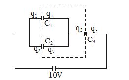
\displaystyle -{{q}_{1}}-{{q}_{2}}+{{q}_{3}}=0,
\displaystyle {{q}_{3}}={{q}_{1}}+{{q}_{2}} ,
\displaystyle {{V}_{1}}=\frac{{{{q}_{1}}}}{{{{C}_{1}}}},{{V}_{2}}={{V}_{1}}=\frac{{{{q}_{2}}}}{{{{C}_{2}}}},{{V}_{3}}=\frac{{{{q}_{3}}}}{{{{C}_{3}}}}=\frac{{{{q}_{1}}+{{q}_{2}}}}{{{{C}_{3}}}}
\displaystyle {{V}_{1}}+{{V}_{3}}=10\Rightarrow \frac{{{{q}_{1}}}}{{{{C}_{1}}}}+\frac{{{{q}_{1}}+{{q}_{2}}}}{{{{C}_{3}}}}=10
\displaystyle {{V}_{1}}={{V}_{2}}\Rightarrow \frac{{{{q}_{1}}}}{{{{C}_{1}}}}=\frac{{{{q}_{2}}}}{{{{C}_{2}}}}
Solving the above two equations we obtain q1 = 25µC
Illustration
A parallel plate capacitor has plates of area A separated by a distance d. A metal block of thickness h is inserted midway between the plates, as shown in the figure. Find the capacitance of the system.
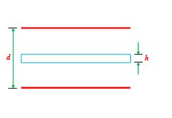
Solution
The system can be idealized as shown in the fig.
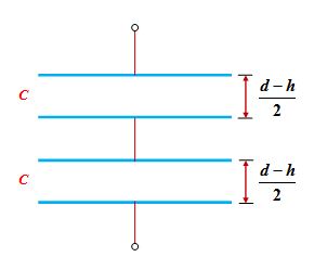
It is a system of two capacitors in series. The capacitance of each capacitor is given by
C = \frac{{{{\varepsilon }_{o}}A}}{{\frac{{d-h}}{2}}}\,=\frac{{2{{\varepsilon }_{o}}A}}{{d-h}}
The equivalent capacitance is
Ceq= \frac{C}{2} = \frac{{{{\varepsilon }_{o}}A}}{{d-h}}
Illustration
The Fig. shown a system of parallel conductors. Each plate is of equal area A and equally separated by d. Find the equivalent capacitance of the system between a and b.
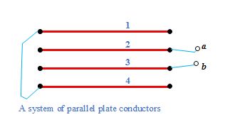
Solution
By joining the points of same potential, the arrangement of conductors may be reduced as shown in the fig
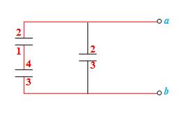
If the capacitance between two successive plates is given by
C = \frac{{{{\varepsilon }_{o}}A}}{d}
then, the equivalent capacitance of the system is given by
Ceq= \frac{{3C}}{2}\,=\frac{3}{2}\,\frac{{{{\varepsilon }_{o}}A}}{d}
Illustration
A charge q is uniformly distributed over a conducting sphere of radius R. Find the energy stored by the sphere in the surrounding space.
Solution
Consider a concentric shell of radius r and thickness dr as shown in the fig.
The energy stored in unit volume is given by
u = \frac{1}{2} \displaystyle {{\varepsilon }_{0}}{{E}^{2}}
Applying Gauss Law, electric fields at a distance r from the centre of the sphere is
E = \frac{1}{{4\pi {{\varepsilon }_{0}}}}\,\frac{q}{{{{r}^{2}}}}
Energy stored in shell of radius r and thickness dr is
dU = 1/2 \displaystyle {{\varepsilon }_{0}}{{E}^{2}} (4pr2dr)
or dU = \frac{1}{2}εo {{\left( {\frac{1}{{4\pi {{\varepsilon }_{o}}}}\,\frac{q}{{{{r}^{2}}}}} \right)}^{2}}(4πr2dr)
dU = \frac{{{{q}^{2}}}}{{8\pi {{\varepsilon }_{o}}}}\,\frac{{dr}}{{{{r}^{2}}}}
The total energy stored can be obtained by integrating the above expression from R to ∞.
U = \frac{{{{q}^{2}}}}{{8\pi {{\varepsilon }_{o}}}}\,\int\limits_{R}^{\infty }{{\frac{{dr}}{{{{r}^{2}}}}}}\,=\frac{{{{q}^{2}}}}{{8\pi {{\varepsilon }_{o}}R}}
Note that the energy stored can also obtained by U = \frac{{{{q}^{2}}}}{{2C}}
Illustration
When a charged capacitor \displaystyle {{C}_{1}} disconnected from the cell of voltage Vis connected to the uncharged capacitor \displaystyle {{C}_{2}} ,Find the final potential difference across the capacitors and energy loss in the process.
Solution
When a charged capacitor is connected to an uncharged capacitor, redistribution of charges occur to equalize the potential difference across each capacitor.
Suppose a capacitor \displaystyle {{C}_{1}} with an initial \displaystyle {{q}_{0}} is connected to an uncharged capacitor \displaystyle {{C}_{2}}, as shown in the figure
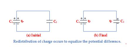
Let q1 and q2 the final charge on capacitors C1 and C2, respectively. Then to equalize the potential difference.
\frac{{{{q}_{1}}}}{{{{C}_{1}}}}\,=\frac{{{{q}_{2}}}}{{{{C}_{2}}}}\,=\,\frac{{{{q}_{1}}\,+{{q}_{2}}}}{{{{C}_{1}}+\,{{C}_{2}}}}=\frac{{{{q}_{o}}}}{{{{C}_{1}}\,+\,{{C}_{2}}}}
Thus \displaystyle {{q}_{1}}={{q}_{0}} \left[ {\frac{{{{C}_{1}}}}{{{{C}_{1}}\,+\,{{C}_{2}}}}} \right]
\displaystyle {{q}_{2}}={{q}_{0}} \left[ {\frac{{{{C}_{2}}}}{{{{C}_{1}}\,+\,{{C}_{2}}}}} \right]
Note that the charge distribution is proportional to the capacitance.
\displaystyle {{q}_{1}} ∝ µ C1 and \displaystyle {{q}_{2}} ∝ µ C2
The initial energy stored in the circuit is
Ui = \frac{{q_{o}^{2}}}{{2{{C}_{1}}}}
and the final energy is
Uf = \frac{{q_{1}^{2}}}{{2{{C}_{1}}}}\,+\frac{{q_{2}^{2}}}{{2{{C}_{2}}}}\,=\frac{{q_{o}^{2}}}{{2({{C}_{1}}+{{C}_{2}})}}
The final energy is less than the initial energy. The difference is lost in the form of electromagnetic waves.
ΔUloss = Ui– Uf = \left( {\frac{{{{C}_{2}}}}{{{{C}_{1}}+\,{{C}_{2}}}}} \right)\,{{U}_{i}}
or \frac{{\Delta {{U}_{{loss}}}}}{{{{U}_{i}}}}\,=\frac{{{{C}_{2}}}}{{{{C}_{1}}\,+\,{{C}_{2}}}}
Illustration
In the circuit shown in figure
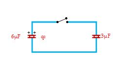
(a) Find the final charge on each capacitor after closing the switch.
(b) Also, find the percentage of energy lost.
Solution
Since charges are distributed proportional to the capacitance, therefore
(a)
Charge on 6µF capacitor is
q6 = qo \left( {\frac{6}{{6+3}}} \right)\,=60\mu C
and on the 3µF capacitor is
q3 = qo \left( {\frac{3}{{6+3}}} \right)\,=\,30\mu C
(b)
\displaystyle \frac{{\Delta {{U}_{{loss}}}}}{{{{U}_{i}}}}\,=\frac{3}{{3+6}}=\,0.333\,\,\,\,\,(or\,\,\,33.3\%)
Illustration
Consider the situation shown in the figure. The capacitor A has a charge q on it whereas B is uncharged. The charge appearing on the capacitor B a long time after the switch is closed is
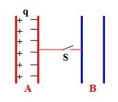
(a) zero (b) q/2
(c) q (d) 2q
Solution
As the negative charge on the plate of capacitor A is bound, it will not move upon closing the switch.
(a)
Dielectrics
A non-conducting material such as glass or wood is called a dielectric. Though the electrons in such materials remain bound within their molecules and thereby preserving the overall neutrality of each molecule, they are affected by external electric field because positive nucleus (protons) and negative charges (electrons) tend to shift in opposite directions.
There are two types of dielectrics :
1.
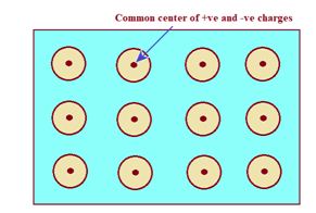
Non-polar dielectrics
In this type of materials, the center of mass of all positive charges in a molecule coincides with the center of mass of all negative charges (electrons) in the absence of external electric field as shown in the diagram given below. Hence, they are not only electrically neutral but also have zero dipole moments.
Now, when external field is switched on, the two centres of charge get slightly separated and each molecule becomes a dipole, having a small dipole moment as shown in the diagram given below
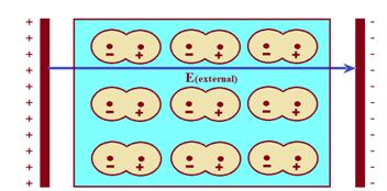
This happens because protons move in the direction of electric field while electrons experience force in the opposite direction. Hence in the presence of electric field, the dielectric gets polarized.
2.
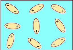
Polar dielectrics
In polar dielectric, such as water, the center of mass of the protons in a molecule does not coincide with the center of mass of electrons even in the absence of electric fields. This happens because of asymmetric shape of the molecules. Thus each molecule behaves as dipole having permanent dipole moment.
In the presence of external electric field, these dipoles tend to align themselves with the electric field as shown in the figure given below
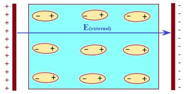
So from above discussion it is clear that inside an external electric field both types of dielectrics are polarized.
Effect Of polarization and dielectric constant
Suppose a dielectric slab is placed in a uniform electric field \displaystyle {{\vec{E}}_{0}}
The electric field will polarize the slab. As discussed above the positive charges of all the molecules will be shifted towards right and negative charges will be shifted towards left. The net effect of the polarization is to produce a positive surface charge on the right face and a negative surface charge on the left surface as shown in the diagram given below.
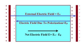
This surface charge sets up an electric field {{\vec{E}}_{p}} in the opposite direction which is less than {{\vec{E}}_{o}} . The net field inside the slab become {{\vec{E}}_{{}}}={{\vec{E}}_{o}}-{{\vec{E}}_{p}}
The ratio of external electric field applied to the net electric field produced in the dielectric is called the dielectric constant of the material normally denoted by K.
Hence {{\vec{E}}_{o}}
The induced charge appearing on the two surfaces is not free to move and is called bound charge.
PROPERTIES OF DIELECTRICS
When a slab of dielectric is inserted to completely fill the space between the plates of a parallel plate capacitor (battery disconnected) as shown in fig. (b)
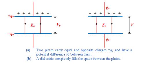
The potential difference between the plates decreases by a factor , called the dielectric constant.
V = \frac{{{{V}_{o}}}}{\kappa }
Where Vo is the original potential difference between the plates
Since V = Ed, therefore, electric field also decreases by a factor
E = \frac{{{{E}_{o}}}}{\kappa }
If we insert the dielectric slab to fill the space between the plates without disconnecting the battery, then the potential difference across the plates does not change.
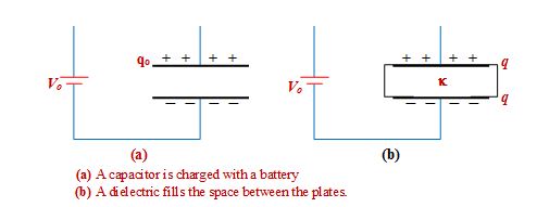
Since the spacing between the plates is also constant, therefore, the electric field intensity between the plates also remain unchanged Vo = Ed
Obviously, the capacitance increases by k by inserting the slab.
C = kCo
Since q = CVo therefore
q = kCoVo = kqo
Charge on the capacitor increases by a factor k.
What happens to the energy stored in the capacitor?
(i) Battery disconnected
Initial energy Ui = \frac{{q_{o}^{2}}}{{2{{C}_{o}}}}
Final energy Uf= \frac{{q_{o}^{2}}}{{2C}} = \frac{{q_{o}^{2}}}{{2\kappa {{C}_{o}}}} = \frac{{{{U}_{i}}}}{\kappa }
The energy stored in the capacitor reduces by a factor k
(ii) Battery connected
Internal energy Ui= \frac{1}{2} Co V_{o}^{2}
Final energy Uf= 1/2C V_{o}^{2} =1/2 kCo V_{o}^{2} = kUi
The energy stored in the capacitor increases by a factor k
The energy density u in the presence of dielectric is given by
u = \frac{1}{2}\,\kappa {{\varepsilon }_{o}}\,{{E}^{2}}
(II) Capacitor with dielectric slab
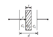
Let a dielectric slab of thickness ‘t’ dielectric constant ‘K’ is placed between the plate, at a distance ‘x’ from one plate.
Let E is a field in a region between the plates filled with air, then field inside dielectric slab is E/K.
Therefore, the potential difference between the plates is
V=E(d-t)+\frac{E}{K}t
Since
E=\frac{\sigma }{{{{\varepsilon }_{o}}}}=\frac{q}{{A{{\varepsilon }_{o}}}}
So
V=\frac{q}{{A{{\varepsilon }_{o}}}}\left[ {(d-t)+\frac{t}{K}} \right]
The capacitance of capacitor is
C=\frac{q}{V}=\frac{{A{{\varepsilon }_{o}}}}{{(d-t)+\,t/K}}
Illustration
A dielectric slab of thickness h and dielectric constant k is inserted into a parallel plate capacitor with plates of area A, separated by a distance d, as shown in the figure. The capacitor is charged to a value qo and the battery is disconnected before inserting the slab.
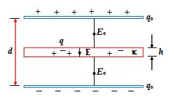
(a) Find the capacitance of the capacitor
(b) Find the magnitude of the induced charges q
Solution
(a)
The electric field strength in air is
Eo = \frac{\sigma }{{{{\varepsilon }_{o}}}}=\frac{{{{q}_{o}}}}{{{{\varepsilon }_{o}}A}}
The electric field in the dielectric is
E = \frac{{{{E}_{o}}}}{\kappa }
The total potential difference between the two plates is
V = Eo (d –h) + Eh = Eo \left[ {d-h+\frac{h}{\kappa }} \right]\,=\frac{{{{q}_{o}}}}{{{{\varepsilon }_{o}}A}}\,\left[ {d\,-h\,+\frac{h}{\kappa }} \right]
Thus, C = \frac{{{{q}_{o}}}}{A}\,=\frac{{{{\varepsilon }_{o}}A}}{{(d-h)\,+\frac{h}{\kappa }}}
(b)
Applying Gauss law for the surface shown in the figure, we have
\oint{{\vec{E}.d\vec{S}\,=\frac{{{{q}_{{net}}}}}{{{{\varepsilon }_{o}}}}}}
EA = \frac{{{{q}_{o}}-q}}{{{{\varepsilon }_{o}}}}
or E = \frac{{{{q}_{o}}}}{{{{\varepsilon }_{o}}A}}\,-\frac{q}{{{{\varepsilon }_{o}}A}} …(i)
Since E = \frac{{{{E}_{o}}}}{\kappa }\,=\frac{{{{q}_{o}}}}{{k{{\varepsilon }_{o}}A}}[/katex …(ii)
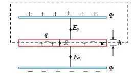
Using (i) and (ii)
\frac{{{{q}_{o}}}}{{\kappa {{\varepsilon }_{o}}A}}\,=\frac{{{{q}_{o}}}}{{{{\varepsilon }_{o}}A}}\,-\frac{q}{{{{\varepsilon }_{o}}A}}
or q = qo \left( {1\,-\frac{1}{k}} \right)
Illustration
Square plates of area 2a2 are filled with dielectric of strength \displaystyle {{k}_{1}} , \displaystyle {{k}_{2}} and \displaystyle {{k}_{3}} as shown in figure. Find Ceq
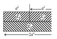
(a) \displaystyle \frac{{{{\varepsilon }_{0}}{{a}^{2}}({{k}_{1}}{{k}_{3}}+{{k}_{2}}{{k}_{3}})}}{{d({{k}_{1}}+{{k}_{2}}+{{k}_{3}})}}
(b) \displaystyle \frac{{2{{\varepsilon }_{0}}{{a}^{2}}({{k}_{1}}{{k}_{3}}+{{k}_{2}}{{k}_{3}})}}{{d({{k}_{1}}+{{k}_{2}}+2{{k}_{3}})}}
(c) \displaystyle \frac{{2{{\varepsilon }_{0}}{{a}^{2}}({{k}_{1}}{{k}_{3}}+{{k}_{2}}{{k}_{3}})}}{{d(2{{k}_{1}}+{{k}_{2}}+2{{k}_{3}})}}
(d) none of these
Solution
The equivalent capacitance circuit is where
\displaystyle {{C}_{1}}=\frac{{{{\varepsilon }_{0}}{{K}_{1}}{{a}^{2}}}}{d},{{C}_{2}}=\frac{{{{\varepsilon }_{0}}{{K}_{2}}{{a}^{2}}}}{d}
and
\displaystyle {{C}_{3}}=\frac{{2{{\varepsilon }_{0}}{{K}_{3}}{{a}^{2}}}}{d}\frac{1}{{{{C}_{{eq}}}}}=\frac{1}{{{{C}_{1}}+{{C}_{2}}}}+\frac{1}{{{{C}_{3}}}}
\displaystyle =\frac{d}{{{{\varepsilon }_{0}}{{a}^{2}}({{k}_{1}}+{{k}_{2}})}}+\frac{d}{{{{\varepsilon }_{0}}{{a}^{2}}2{{k}_{3}}}}
\displaystyle {{C}_{{\text{eq}}}}=\frac{{2{{\varepsilon }_{0}}{{a}^{2}}({{k}_{1}}+{{k}_{2}}){{k}_{3}}}}{{({{k}_{1}}+{{k}_{2}}+2{{k}_{3}})d}}
Illustration
A capacitor has charge 50 µC. When the gap between the plates is filled with glass wool 120 µC charge flows through the battery. The dielectric constant of glass wool is
(a) 3.4
(b) 1.4
(c) 2.4
(d) 4.4
Solution
\displaystyle K=\frac{{{Q}’}}{Q}=\frac{{120+50}}{{50}}=3.4
Ans. (a)
Illustration
A slab of material of dielectric constant K has the same area as the plates of a parallel-plate capacitor but has a thickness (3/4) d, where d is the separation of the plates. How is the capacitance changed when the slab is inserted between the plates?
Solution:
Let {{E}_{0}}=V/d be the electric field between the plates when there is no dielectric and the potential difference is {{V}_{0}}. If the dielectric is now inserted, the electricfield in the dielectric will be E={{E}_{0}}/K. The potential difference will then be
V={{E}_{0}}\left( {\frac{1}{4}d} \right)+\frac{{{{E}_{0}}}}{K}\left( {\frac{3}{4}d} \right)
={{E}_{0}}d\left( {\frac{1}{4}+\frac{3}{{4K}}} \right)={{V}_{0}}\frac{{K+3}}{{4K}}
The potential difference decreases by the factor \frac{{(K+3)}}{{4K}} while the free charges {{Q}_{0}} on the plates remains unchanged. The capacitance thus increases:
C=\frac{{{{Q}_{0}}}}{V}=\frac{{4K}}{{K+3}}\frac{{{{Q}_{0}}}}{{{{V}_{0}}}}=\frac{{4K}}{{K+3}}{{C}_{0}}
Objective Assignment
Q.1
If the energy of a 100 µF capacitor charged to 6 kV could all be used to lift a 50 kg mass, what would be the greatest vertical height through which mass could be raised ?
(a) 0.6 mm
(b) 3.6 m
(c) 1.2 mm
(d) 12 m
Ans.. (b)
Q.2
The energy stored in a condenser of capacity C which has been raised to a potential V is given by
(a) \displaystyle \frac{1}{2}CV
(b) \displaystyle \frac{1}{2}C{{V}^{2}}
(c) \displaystyle CV
(d) \displaystyle \frac{1}{{2VC}}
Ans. (b)
Q.3
Capacity of a capacitor is 48 µF. When it is charged from 0.1C to 0.5, change in the energy stored is
(a) 2500 J
(b) \displaystyle 2.5\times {{10}^{{-3}}}J
(c) \displaystyle 2.5\times {{10}^{6}}J
(d) \displaystyle 2.42\times {{10}^{{-2}}}J
Ans. (d)
Q.4
What is called electrical energy tank ?
(a) Resistor
(b) Inductor
(c) Capacitor
(d) Motor
Ans. (c)
Q.5
The capacitance of a metallic sphere is 1µF, then its radius is nearly
(a) 1.11 m
(b) 10 m
(c) 9 km
(d) 1.11 cm
Ans. (c)
Q.6
A capacitor is charged by a battery and the energy stored is U. The battery is now removed and the separation distance between the plates is doubled. The energy stored now is
(a) \displaystyle \frac{U}{2}
(b) U
(c) 2U
(d) 4U
Ans. (c)
Q.7
In the circuit shown in the figure, the potential difference across the 4.5 µF capacitor is
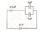
(a) \displaystyle \frac{8}{3}V
(b) 4V
(c) 6V
(d) 8V
Ans. (d)
Q.8
In the connections shown in the adjoining figure, the equivalent capacity between points A and B will be
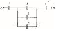
(a) \displaystyle \frac{{13}}{6}
(b) \displaystyle \frac{6}{{13}}
(c) 6
(d) 13
Ans. (b)
9.
A parallel plate capacitor of capacitance C is connected to a battery of emfV. If a dielectric slab is completely inserted between the plates of the capacitor and battery remains connected, then electric field between plates
(a) decreases
(b) increases
(c) remains constant
(d) may be increase or may be decrease
Ans (c)
10.
In a parallel-plate capacitor of capacitance C, a metal sheet is inserted between the plates, parallel to them. The thickness of the sheet is half of the separation between the plate. The capacitance now becomes
(a) 4C
(b) 2C
(c) C/2
(d) C/4
Ans (b)
11.
Two capacitors of capacitance 3 \displaystyle \mu Fand 6 \displaystyle \mu F are charged to a potential of 12 V each. They are now connected to each other, with the positive plate of one to the negative plate of the other. Then
(a) the potential difference across 3 \displaystyle \mu Fis zero
(b) the potential difference across 3 \displaystyle \mu Fis 4 V
(c) the charge on 3 \displaystyle \mu Fis zero
(d) the charge on 3 \displaystyle \mu Fis 10 \displaystyle \mu C
Ans (d)
12.
In the circuit shown, a potential difference of 60V is applied across AB. The potential difference between the points M and N is
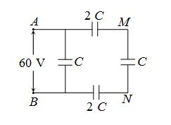
(a) 10 V
(b) 15 V
(c) 20 V
(d) 30 V
Ans (d)
13.
Capacitance of a capacitor becomes \frac{4}{3}times its original value if a dielectric slab of thickness t = d/2 is inserted between the plates (d = separation between the plates). The dielectric constant of the slab is
(a) 2
(b) 4
(c) 6
(d) 8
Ans (a)
14.
In the circuit shown in the figure, C = 6 \displaystyle \mu F. The charge stored in the capacitor of capacity C is
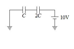
(a) zero
(b) 90 \displaystyle \mu C
(c) 40 \displaystyle \mu C
(d) 60 \displaystyle \mu C
Ans (c)
15.
The distance between the plates of an isolated parallel plate condenser is 4mm and potential difference is 60 volts. If the distance between the plates is increased to 12mm, then
(a) The potential difference of the condenser will become 180 volts.
(b) The P.D. will become 20 volts.
(c) The P.D. will remain unchanged.
(d) The charge on condenser will reduce to one third
Ans (a)
16.
Two spherical conductors A and B of radii a andb (b>a) are placed concentrically in air. The two are connected by a copper wire as shown in figure. Then the equivalent capacitance of the system is
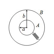
(a) \frac{{4\pi {{\varepsilon }_{0}}ab}}{{b-a}}
(b) 4\pi {{\varepsilon }_{0}}(a+b)
(c) 4\pi {{\varepsilon }_{0}}b
(d) 4\pi {{\varepsilon }_{0}}a
Ans (c)
Subjective Assignment
Q.1
Define the dielectric constant of a medium. What is its unit ?
Q.2
A parallel plate capacitor with air between the plates has a capacitance of 8 pF
(1pF = 10–12 F). What will be the capacitance if the distance between the plates is reduced by half, and the space between them is filled with a substance of dielectric constant 6?
Q.3
A 12pF capacitor is connected to a 50V battery. How much electrostatic energy is stored in the capacitor?
Q.4
What is the area of the plates of a 2 F parallel plate capacitor, given that the separation between the plates is 0.5 cm?
Q.5
Distinguish between polar and non-polar dielectric.
Q.6
What is the area of the plates of a 2F parallel plate capacitor having separation between the plates is 0.5 cm ?
Q.7
Net capacitance of three identical capacitors in series is 1 \displaystyle \mu F. What will be their net capacitance if connected in parallel ?
Find the ratio of energy stored in the two configurations if they are both connected to the same source.
Q8
Three capacitors each of capacitance 9 pF are connected in series.
(a) What is the total capacitance of the combination?
(b) What is the potential difference across each capacitor if the combination is connected to a 120 V supply?
Q.9
Three capacitors of capacitances 2 pF, 3 pF and 4 pF are connected in parallel.
(a) What is the total capacitance of the combination?
(b) Determine the charge on each capacitor if the combination is connected to a 100 V supply.
Q.10
An electrical technician requires a capacitance of 2 μF in a circuit across a potential difference of 1 kV. A large number of 1 μF capacitors are available to him each of which can withstand a potential difference of not more than 400 V. Suggest a possible arrangement that requires the minimum number of capacitors.
Q.11
In a Van de Graaff type generator a spherical metal shell is to be a 15 × 106 V electrode. The dielectric strength of the gas surrounding the electrode is 5 × 10⁷ Vm–1. What is the minimum radius of the spherical shell required?
Q.12
A dielectric slab of thickness ‘t’ is kept in between the plates, each of area “A”, of a parallel plate capacitor separated by a distance ‘d’. Derive an expression for the capacitance of this capacitor for \displaystyle t\,<<\,d.
Q.13
A parallel plate capacitor is charged by a battery. After sometime the battery is disconnected and a dielectric slab with its thickness equal to the plate separation is inserted between the plates. How will (i) the capacitance of the capacitor, (ii) potential difference between the plates and (ii) the energy stored in the capacitor be affected ? Justify your answer in each case.
Q.14
A parallel plate capacitor is charged to a potential difference V by a dc source. The capacitor is then disconnected from the source. If the distance between the plates is doubled, state with reason how the following will change :
(i) electric field between the plates.
(ii) capacitance, and
(iii) energy stored in the capacitor.
Q.15
Show that the capacitance of a spherical conductor is \displaystyle 4\pi {{\in }_{0}}to time the radius of the spherical conductor.
Q.16
Two large, thin metal plates are parallel and close to each other. On their inner faces, the plates have surface charge densities of opposite signs and of magnitude 17.0 × 10⁻²² C/m2. What is E: (a) in the outer region of the first plate, (b) in the outer region of the second plate, and (c) between the plates?
Q.17
A 600pF capacitor is charged by a 200V supply. It is then disconnected from the supply and is connected to another uncharged 600 pF capacitor. How much electrostatic energy is lost in the process?
Q.18
The plates of a parallel plate capacitor have an area of 90 cm2 each and are separated by
2.5 mm. The capacitor is charged by connecting it to a 400 V supply.
(a) How much electrostatic energy is stored by the capaci
(b) View this energy as stored in the electrostatic field between the plates, and obtain the energy per unit volume u. Hence arrive at a relation between u and the magnitude of electric field E between the plates.
Q.19
A 4 μF capacitor is charged by a 200 V supply. It is then disconnected from the supply, and is connected to another uncharged 2 μF capacitor. How much electrostatic energy of the first capacitor is lost in the form of heat and electromagnetic radiation?
Q.20
A cylindrical capacitor has two co-axial cylinders of length 15 cm and radii 1.5 cm and
1.4 cm. The outer cylinder is earthed and the inner cylinder is given a charge of 3.5 μC. Determine the capacitance of the system and the potential of the inner cylinder. Neglect end effects (i.e., bending of field lines at the ends).
Q.21
A parallel plate capacitor is to be designed with a voltage rating 1 kV, using a material of dielectric constant 3 and dielectric strength about 107 Vm–1. (Dielectric strength is the maximum electric field a material can tolerate without breakdown, i.e., without starting to conduct electricity through partial ionisation.) For safety, we should like the field never to exceed, say 10% of the dielectric strength. What minimum area of the plates is required to have a capacitance of 50 pF?
Q.22
(a) Show that in a parallel plate capacitor, if the medium between the plates of a capacitor is filled with an insulating substance of dielectric constant K, its capacitance increases.
(b) Deduce the expression for the energy stored in a capacitor of capacitance C with charge Q.
Q.23
(a) In a parallel plate capacitor with air between the plates, each plate has an area of 6 × 10⁻³ m2 and the distance between the plates is 3 mm. Calculate the capacitance of the capacitor. If this capacitor is connected to a 100 V supply, what is the charge on each plate of the capacitor?
(b) Explain what would happen if in the capacitor a 3 mm thick mica sheet (of dielectric constant = 6) were inserted between the plates,
(i) while the voltage supply remained connected.
(ii) after the supply was disconnected.
Q.24
A spherical capacitor has an inner sphere of radius 12 cm and an outer sphere of radius
13 cm. The outer sphere is earthed and the inner sphere is given a charge of 2.5 μC. The space between the concentric spheres is filled with a liquid of dielectric constant 32.
(a) Determine the capacitance of the capacitor.
(b) What is the potential of the inner sphere?
Q.25
(a) Deduce the expression for the energy stored in a charged capacitor.
(b) Show that the effective capacitance, C, of a series combination, of three capacitors, \displaystyle {{C}_{1}}, \displaystyle {{C}_{2}} and \displaystyle {{C}_{3}} is given by \displaystyle C\,=\,\frac{{{{C}_{1}}{{C}_{2}}{{C}_{3}}}}{{\left( {{{C}_{1}}{{C}_{2}}\,+\,{{C}_{2}}{{C}_{{3\,}}}+\,{{C}_{3}}{{C}_{1}}} \right)}}
Q.26
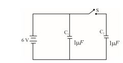
Figure shows two identical capacitors, \displaystyle {{C}_{1}} and \displaystyle {{C}_{2}}, each of 1 \displaystyle \mu F capacitance connected to a battery of 6V. Initially switch ‘S’ is closed. After sometime ‘s” is left open and dielectric slabs of dielectric constant K=3 are inserted to fill completely the space between the plates of the two capacitors. How will the (i) charge and (ii) potential difference between the plates of the capacitors be affected after the slabs are inserted ?
Q.27
Three identical capacitors \displaystyle {{C}_{1}},\,\,{{C}_{2}} and \displaystyle {{C}_{3}} of capacitance \displaystyle 6\mu F each are connected to a 12V battery as shown.
Find
(a) Charge on each capacitor.
(b) Equivalent capacitance of the network.
(c) Energy stored in the network of capacitors.
Q.28
Two parallel plate capacitor, X and Y, have the same area of plates and same separation between them. X has air between the plates while Y contains a dielectric medium of \displaystyle {{\in }_{r}}\,=\,4.
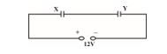
(a) Calculate capacitance of each capacitor if equivalent capacitance of the combination is \displaystyle 4\mu F.
(b) Calculate the potential difference between the plates of X and Y.
(c) What is the ratio of electrostatic energy stored in X and Y ?
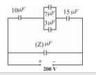
Q.29
A system of capacitors, connected as shown, has a total energy of 160 mJ stored in it. Obtain the value of the equivalent capacitance of this system and the value of Z.
Q.30
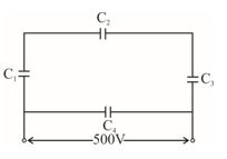
A network of four capacitors each of 12 \displaystyle \mu F capacitance is connected to a 500 V supply as shown in the figure. Determine (a) equivalent capacitance of the network and (b) charge on each capacitor.
Q.31
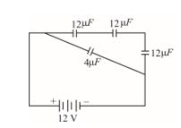
Four capacitors of values 12 \displaystyle \mu F, 12 \displaystyle \mu F, 12 \displaystyle \mu F and 4, are connected to a 12V battery as shown in the figure. Determine the (i) equivalent capacitance of the network. (ii) the charge on each capacitor.
Q.32
The equivalent capacitance of the combination between A and B in the given figure is \displaystyle 4\,\mu F.
(a) Calculate capacitance of the capacitor C.
(b) Calculate charge on each capacitor if a 12V battery is connected across terminals A and B.
(c) What will be the potential drop across each capacitor?
Q.33
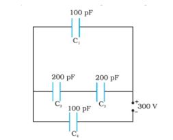
Obtain the equivalent capacitance of the network in Fig.. For a 300 V supply, determine the charge and voltage across each capacitor.
Q.34
A spherical capacitor consists of two concentric spherical conductors, held in position by suitable insulating supports (Fig.). Show that the capacitance of a spherical capacitor is given by \displaystyle \frac{{4\pi {{\varepsilon }_{0}}{{r}_{1}}{{r}_{2}}}}{{{{r}_{1}}-{{r}_{2}}}}.
where r1 and r2 are the radii of outer and inner spheres, respectively.