Video Lecture

Theory For Making Notes

Kirchhoff’s Laws 

The two laws of Kirchoff are based on the conservation of charge and the conservation of energy, respectively. When applied to any circuit, the laws provide us with a set of simultaneous equations from which we can solve for the current through any resistor. Kirchhoff’s laws are general and can be applied to any type of circuit.


Kirchhoff’s Current Law (KCL)

At any circuit junction the sum of the currents entering the junction must equal the sum of the current leaving the junction.

I1 – I2 + I3 – I4 = 0

or         I1 + I3 = I­2 + I4

It is based on conservation of charge. As current flows through various branches of a circuit, nowhere the charges accumulate or disappear.

Kirchhoff’s Voltage Law (KVL)

The sum of voltage changes across all the circuit elements found when traversing one direction around any closed circuit-loop must be zero.

It is based on energy conservation. As charge q moves around a complete circuit loop, its energy gains and losses must total zero.

How to apply Kirchhoff’s law in a circuit?

Assume currents along with their directions in each branch of the complex circuit. Itis not always  easy to correctly guess the current direction-no problem if one chooses the wrong direction. After solving the problem, if the numerical value for the current comes out negative, it indicates that the particular current is in the opposite direction from the original guess.

After assuming currents in each branch, we pick a point and begin to walk (mentally) around a circuit loop. As we traverse each resistor or battery we must write down the voltage change for that element according to the following four rules.

1.

If we traverse through a battery from the negative terminal to the positive terminal, the change in voltage is +E.

2.

If we traverse through a battery from the positive terminal to the negative terminal, the change in voltage is -E.

3.

If a resistor is traversed in the same direction as the assumed current flow, the change in potential is -IR

4.

If a resistor is traversed in the direction opposite from the assumed current flow, the change in potential is +IR.


The set of equations obtained by use Kirchoff’s voltage law will be independent provided that each new loop equation contains a voltage change not included in a previous equation.

Illustration

In figure, find I1, I2 and I3 if switch S is open.

Solution

(a)    

When S is open, I3 = 0, because no current can flow through the open switch. Applying the KCL the to point a, we get

I1 + I3 = I2     or     I2 + I1 + 0 = I1

Applying the KVL to loop acdba. we get

–  7I1 + 12 – 9 – 8I2  = 0                                                                   … (i)

Because I2 = I1, (i) becomes

15I1 = 3     or     I1 = 0.20A

 Also, I2 = I1 = 0.20A.


Note that this is the same result that one would obtain by replacing the two batteries by a single 3V battery.


Illustration

In figure, find I1, I2 and I3 if switch S is closed.

Solution

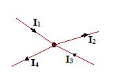
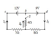
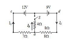
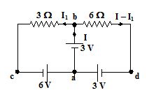
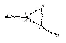
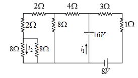
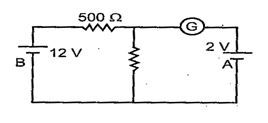
With the switch S closed, I3 is no longer known to be zero. Therefore, by applying the KCL point a gives

I1 + I3 = I2                                                 … (i)

Applying KVL to loop acba.


– 7I1 + 12 + 4I3 = 0      … (ii)


and loop abda gives

 – 9 – 8I2 – 4I3 = 0                                     … (iii)

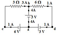
After solving equation (i), (ii) and (iii) for I1, I2 and I3. From (iii), we get

I3 = –2I2 – 2.25


Substituting this in (ii) gives

+ 12 – 7I1 – 9 – 8I2 = 0     or     7I1 + 8I2 = 3


Also substituting for I3 in (i) gives

I1 – 2I2 – 2.25 = I2     or    I1 = 3I2 + 2.25


Substituting this value in the previous equation,

 21I2 + 15.75 + 8I2 = 3     or     I2 = – 0.44A


Using this in the equation for I1 gives

I1 = 3 (– 0.44) + 2.25 = – 1.32 + 2.25 = 0.93A


Note that the minus sign is a part of the value we have found for I2. It must be carried along with its numerical value. Now we can used (i) to find


I3 = I2I1 = (– 0.44) – 0.93 = – 1.37A


Note that this problem could not be solved by simple parallel-or series-resistance techniques and applying the superposition principle
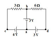
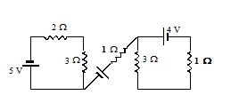
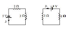
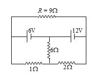
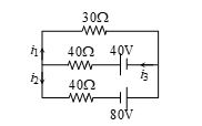
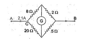
 

Illustration

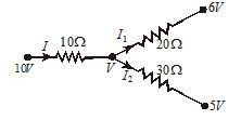
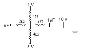
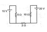
Find the current through each branch of the circuit shown.

Solution

The current assumed in the circuit as shown in the figure. Applying KCL to loop abca

+3 – 3I1 + 6 = 0

or      I1 = 3A

Applying KVL to loop abda

+3-6 (I – I1) + 3 = 0

or      I – I1 = 1

I = 1 + I1 = 4A

The current through each branch is shown in the figure.

Illustration

In the given circuit find the current passing through each branch.

Solution

Kirchhoff’s current law does not allow any current through 1 Ω resistor of the circuit. Now the circuit will become as shown in figure.

Using KVL, {{I}_{1}}=1A, {{I}_{2}}=1A


Illustration

Find the equivalent resistance between A and B in the given circuit.

Solution:             

The given circuit can be redrawn as shown in figure

It is balanced Wheatstone Bridge.  So, equivalent resistance =R.


Illustration

Twelve wires, each of resistance r ohms are connected in the form of a skeleton cube. Find the equivalent resistance of the cube when the current enters at one corner and leaves at the diagonally opposite corner.

Solution:     

Let a current of magnitude 6I  enter at A and leave at G. The distribution of current in the various arms is shown in figure

Let R be the equivalent resistance of the cube between points A and G and r be the resistance of each side of the cube.


Applying Kirchhoff’s loop law to the closed loop ADCGA, we get


2Ir+Ir+2Ir=E


or      5Ir=E                                                                                 … (i)


or      E=(5I)\,r


But    E=(6I)\,R     … (ii)


6IR=5Ir


or      R=\frac{5}{6}r


Illustration

Find the equivalent resistance of the network shown in the figure between the points a and b.

Solution:             

Step-1:

The equivalent circuit of the network is shown in figure A, which is a Wheatstone bridge

Since \frac{P}{Q}=\frac{R}{S}


or      \frac{r}{r}=\frac{r}{r} , so the resistance between c and d can be removed without affecting the circuit. Thus the circuit reduced to as figure (B).


Now, the resistor ac and cb are in  series, so they can be replaced by a single resistor of resistance (r+r)=2r.


Similarly, resistor ad and db can also be replaced by a single resistor of resistance (r+r)=2r . These two resistors of resistances 2r each are in parallel as shown in figure (C).


Step-2.   

The equivalent resistance between a and b is given by


\frac{1}{{{{r}_{{eq}}}}}=\frac{1}{{2r}}+\frac{1}{{2r}}=\frac{2}{{2r}}=\frac{1}{r}


or    {{r}_{{eq}}}=r


Illustration

Find current I in the given circuit.

(1) 0.2 A                  (2) 0                (3) 9.1 A                                (4) None of these


Solution:

Apply junction law


I={{I}_{1}}+{{I}_{2}}


\frac{{10-V}}{{10}}=\frac{{V-6}}{{20}}+\frac{{V-5}}{{30}}


Or   10-V=\frac{{V-6}}{2}+\frac{{V-5}}{3}


10+\frac{6}{2}+\frac{5}{3}=V\left( {\frac{1}{2}+\frac{1}{3}+3} \right)


or    60+18+10=V(3+2+6)    i.e. 88 = 11V.


so,  V=8\,volt and   I=0.2A                              


Then correct choice is (1)


Equivalent Resistance of Network


There are many techniques to find equivalent or effective resistance between any two terminals of a network. A special skills is to be developed to decide which technique would be easier to use for the given network.


Wheatstone Bridge


If \frac{P}{Q}=\frac{R}{S}


The bridge is balanced. Under balanced condition, points B and D are at same potential and no current flows through the resistance G. Therefore, while calculating the equivalent resistance between A and C, the resistance G is not considered,

\frac{1}{{{{R}_{{\text{eq}}}}}}=\frac{1}{{(P+Q)}}+\frac{1}{{(R+S)}}      …(1)

It is interesting to note that under balanced conditions, the points B and D may be treated as shorted, so that the equivalent circuit becomes as shown. The equivalent resistance between A and C is then given as

{{R}_{{eq}}}=\frac{{P\times R}}{{P+R}}+\frac{{Q\times S}}{{Q+S}}    …..(2)

The result obtained from Eqn (ii) will be the same as that obtained from Eqn (i)

If P = Q = R = S = r, which is usually the case is most of the problems, Req = r.

Note

(1)  

If identical resistances (or capacitances, or inductances, or any combinations of them) are connected to form a wheatstone bridge, the net resistance of the bridge is same as the individual resistance. So if 5 capacitances, each of value 1 μF are connected to form a wheatstone bride, the net capacitance would be 1 μF.

(2)  

Following are some of the network which appear to be different from each other, but electrically all are same as wheatstonebridge :

In all the circuits, if R1/R2 = R3/R4, the bridge is balanced. Then the resistance R5 can be ignored altogether.


(3)  

If the wheatstone bridge is not balanced or Req is to be calculated between points other than A and C, above theory will not hold good and the problem must be solved by applying Kirchhoff’s laws.

Illustration

Calculate the equivalent resistance of the networks shown, between the points A and C.

Solution

A careful study reveals that these networks are balanced wheatstone bridge as (P/Q) = (R/S). No current flows through resistance G. Its presence or absence does not affect the bridge.


For Fig. (A)


Req = (2 + 3)  is parallel with  (4 + 6) = 5  is parallel with 10 = \frac{{5\times 10}}{{5+10}}=\frac{{\text{10}}}{\text{3}}\text{  }\!\!\Omega\!\!\text{ }


For Fig. (B)


Req = (R + Q) is parallel with (R + S) = R


For Fig. (C)


Req = (R + 2R) is parallel with (2R + 4R) = 2R

Illustration

Calculate the effective resistance between points A and C.

Solution

Consider that the given network is made up of two parts connected between points A and C, in parallel.

The part below the dotted line is single resistance R. The part above the dotted line is a wheatstone bridge with all the five resistances being identical to resistance R. Therefore, the equivalent resistance f this balanced wheatstone bridge is simply R.


Thus, we have effectively two resistances, each of value R, connect in parallel between A and C.


Req = R||R = \frac{\text{R}}{\text{2}}


Chain of Dissolving Loops

Consider the network as shown in figure. The network consists of 31 loops. We have to find the equivalent resistance between A and B

It can be easily analysed that if we simplify the last loop (i.e. 31st) then we obtain the pattern which is similar to the precious one.

It is obvious from the above figure that the result obtained after simplifying the 30th loop is also the same. Hence, after simplifying all the 31 loops, we obtain a single loop as follows:

The equivalent resistance between A and B is 2Ω.

In general, the equivalent resistance of such a network as shown in figure is given by

\displaystyle {{R}_{0}}=\sqrt{{r(r+2R)}}-r

Chain of Infinite Loops

The figure represents chain of infinite loops. In this network, we have to find the equivalent resistance between A and B.

In this case, if we remove the first repeating unit, then the network reduces to a pattern as shown below.

Since the pattern extends upto infinity, therefore, removing one loop from it does not affect the equivalent resistance. That is, if R0 is the equivalent resistance between A and B, then the equivalent resistance between C and D is also R0.


Thus, the network reduces to

Now, the equivalent resistance between A and B is


\displaystyle {{R}_{{AB}}}=r+\frac{{R{{R}_{0}}}}{{R+{{R}_{0}}}}


Since RAB­= R0, therefore,


R0 = \displaystyle r+\frac{{R{{R}_{0}}}}{{R+{{R}_{0}}}}


or         \displaystyle R_{0}^{2}-r{{R}_{0}}-rR=0


Solving the above quadratic equation, we get


\displaystyle {{R}_{0}}=\frac{{r\pm \sqrt{{{{r}^{2}}+4rR}}}}{2}


\displaystyle {{R}_{0}}=\frac{r}{2}\left[ {1+\sqrt{{1+\frac{{4R}}{r}}}} \right]


Since R0 cannot be negative, therefore, the negative sign is omitted.


Illustration

Determine the equivalent resistance of the following infinite network.

Solution

Here, r = 1Ω and R = 2Ω

By using the equation (   ), we obtain

\displaystyle {{R}_{{AB}}}=\frac{r}{2}\left[ {1+\sqrt{{1+\frac{{4R}}{r}}}} \right]

or         \displaystyle {{R}_{{AB}}}=\frac{1}{2}\left[ {1+\sqrt{{1+\frac{{4(2)}}{{1r}}}}} \right]=\frac{1}{2}\,\,[1+3]=2\Omega


Illustration

Find RAB for the following circuit, each individual resistance being R.

Solution

If we draw the imaginary line ACB, the lower half of the circuit is mirror image of the upper half. So, the given circuit is equivalent to

\displaystyle {{R}_{{AB}}}=\frac{1}{2}\left[ {R+\frac{1}{{\frac{1}{R}+\frac{1}{{2R}}}}+R} \right]


\displaystyle =\frac{1}{2}\left[ {2R+\frac{{2R}}{3}} \right]=\frac{{4R}}{3}


If students try to solve this question by Kirchhoff’s rules directly, it will become a lengthy solution.


Illustration

Find RAB for the following circuit, each individual resistance being R.

Solution

The above circuit is equivalent to the following circuit.

Now it, is easy to get the result \displaystyle {{R}_{{AB}}}=\frac{{7R}}{5}

Practice Questions (Level-1)

Q.1

In the circuit shown if point O is earthed, the potential of point X is equal to

(a)     10 V                     

(b)     15 V

(c)     25 V                     

(d)     12.5 V    

Ans.  (b)

Q.2

The current in the arm CD in the circuit shown in the figure will be

Q.3

In the given circuit, find the equivalent resistance between point A and B.

(a)     18 W                 

(b)     12 W

(c)     20 W                 

(d)      27 W

Ans.  (b)

Q.4

In the given circuit diagram. Find the value of current in resistance R.

(a) 2 A                                  

(b)  \frac{3}{2}A

(c) 1 A                                  

(d) 4 A

Ans :  a

Q.5

The circuit as shown in figure. The ratio of current  is

(a)    2                   

(b)    8

(c)    0.5               

(d)    4

Ans.  (b)

Q.6

In the given circuit the current i1 is 

(a)   0.4 A                   

(b)   –0.4 A

(c)   0.8 A                   

(d)   –0.8 A

Ans.  (b)

Q.7

The measurement of voltmeter (ideal) in the following circuit is 

(a)    2.4 V                 

(b)     zero

(c)    4.0 V                 

(d)     6.0 V

Ans.  (d)

Q.8

If resistance of each wire in the network shown is r, the equivalent resistance between A & C is equal to

(a)    r       

(b)    \frac{r}{2}

(c)    \frac{{2r}}{3}

(d)    \frac{{3r}}{2}

Q.9

Figure shows a network of a capacitor and resistors. The charge on capacitor in steady state is

(a)     4 mC             

(b)      6 mC

(c)     10 mC           

(d)    16 mC  

Ans.  (d)

Q.10

In the arrangement shown, the magnitude of each resistance is  The equivalent resistance between O and A is given by  

(a)          \frac{{14}}{{15}}\Omega                           

(b)          \frac{7}{{15}}\Omega

(c)          \frac{4}{3}\Omega                                       

(d)          \frac{5}{6}\Omega

Ans.  (a)

Q.11

Two cells with the same emf  E and different internal resistances r1 and r2 are connected in series to an external resistance R. The value of R so that the potential difference across the first cell be zero is 

(a) \sqrt{{{{r}_{1}}{{r}_{2}}}}                      

(b) {{r}_{1}}+{{r}_{2}}                                       

(c) {{r}_{1}}-{{r}_{2}}                                        

(d) \frac{{{{r}_{1}}+{{r}_{2}}}}{2}

Ans : (c)

Practice Questions (Level-2)

Q.1

What is the p.d. between the terminals A and B ?

(a)    12 V                      

(b)    24 V                  

(c)    36 V                  

(d)    48 V

Ans.  (b)

Q.2

What is the energy stored in the capacitor ?  

(a)    72 \displaystyle \mu J

(b)    96 \displaystyle \mu J 

(c)    96 \displaystyle mJ 

(d)    96 \displaystyle MJ

Ans.  (b)

Q.3

What is approximately the potential difference across A and B ?  

(a)      1 V

(b)       2V                         

(c)       –1V                    

(d)       –2V

Ans.  (b)

Q.4

What is the energy stored in the capacitor of capacitance 3 \displaystyle \mu F ?  

(a)      \displaystyle 5.9\,\times \,{{10}^{{-5}}}J     

(b)      \displaystyle 5.8\,\times \,{{10}^{{-5}}}J

(c)      \displaystyle 5.7\,\times \,{{10}^{{-5}}}J     

(d)      \displaystyle 5.6\,\times \,{{10}^{{-5}}}J

Ans.  (a)

Q.5

The current in 2 \displaystyle \Omega resistor is :  

(a)      0                            

(b)      2A                     

(c)      4A                     

(d)      1A

Ans.  (a)

Q.6

In the given circuit in the final voltage drop across the capacitor C is :

(a)    \displaystyle \frac{{V{{r}_{1}}}}{{{{r}_{1}}+{{r}_{2}}}}

(b)    \displaystyle \frac{{V{{r}_{2}}}}{{{{r}_{1}}+{{r}_{2}}}} 

(c)    \displaystyle \frac{{V\left( {{{r}_{1}}+{{r}_{2}}} \right)}}{{{{r}_{2}}}}        

(d)    \displaystyle \frac{{V\left( {{{r}_{1}}+{{r}_{2}}} \right)}}{{{{r}_{1}}\,+\,{{r}_{2}}+{{r}_{3}}}}

Ans.  (b)

Q.7

In the circuit, the galvanometer G shows zero deflection.  If the batteries A and B have negligible internal resistance, the value of the resistor R will be :

(a)    200 \displaystyle \Omega

(b)    100 \displaystyle \Omega                        

(c)    500 \displaystyle \Omega                            

(d)    1000 \displaystyle \Omega

Ans.  (b)


Q.8

The figure shows two metal plats A and B which are square in shape and have same thickness t. The ratio of resistance of A to that of B is :         

(a)  1 : 2                       

(b) 2 : 1                  

(c) 1 : 1

(d) 1 : 4

Ans.  (c)

Q.9

In the given figure when galvanometer shows no deflection, the current (in amp) flowing through 5 ohm resistance will be :  

(a)   0.6                             

(b)   0.5                    

(c)   1.5

(d)    2.0

Ans.  (a)

Q.10

In the Wheatstone bridge shown, P = 2 \displaystyle \Omega , Q=3 \displaystyle \Omega , R = 6 \displaystyle \Omega and S 8 \displaystyle \Omega . In order to obtain balance, shunt resistance across S must be :         

(a)    2 \displaystyle \Omega     

(b)    3 \displaystyle \Omega

(c)    6 \displaystyle \Omega

(d)    8 \displaystyle \Omega

Ans.  (d)