Video Lecture
Theory For Making Notes
Potentiometer
A potentiometer is an instrument which allows the measurement of potential difference without drawing any current from the circuit being measured. Hence, it acts as an infinite-resistance voltmeter.
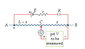
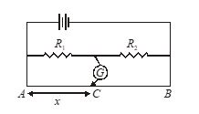
The resistance between A and B is a uniform wire of length L, with a sliding contact C at a distance x and B. The potential difference V is measured by sliding the contact until the galvanometer G reads zero. The no-deflection condition of the galvanometer ensures that there is no current through the branch containing G and the potential difference to be measured. The length x for no-deflection is called as the balancing length.
If l is the resistance per unit length of the wire AB, under balanced condition (i.e., when no current is indicated by galvanometer G), the pd to be measured is given as
\displaystyle V={{V}_{{CB}}}={{V}_{{AB}}}\frac{{{{R}_{{CB}}}}}{{{{R}_{{AB}}}}}={{V}_{{AB}}}\frac{{\lambda \left( x \right)}}{{\lambda L}}
= \left( {\frac{{{{V}_{{\text{AB}}}}}}{L}} \right)\times x
The ratio VAB/L is called the potential gradient in the wire AB.
Comparing Two Cells using Potentiometer
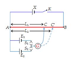
A potentiometer is commonly used for comparison of emfs of cells. A battery X is connected across a long uniform wire AB. The cells E1 and E2 (whose emfs are to be compared) are connected as shown along with a galvanometer.
First the key S1 is pressed which brings E1 in the circuit. The sliding contact C is moved till the galvanometer shows no deflection. Let the length AC = L1. Next S1 is opened and S2 is closed. This brings E2 in the circuit. Let C’ be the new null point and let AC’ = L2. Then, clearly,
\displaystyle \frac{{{{E}_{1}}}}{{{{E}_{2}}}}=\frac{{{{L}_{1}}}}{{{{L}_{2}}}}
Measurement of Internal Resistance of a Cell
A potentiometer can be used to find the internal resistance of a cell. First the emfE of the cell is balanced against a length AC = L. A known resistance R is then connected across the cell as shown. The terminal voltage V is now balanced against a smaller length AC’ = L’.
Then, \displaystyle \frac{E}{V}=\frac{L}{{{L}’}}
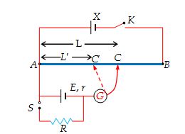
But we know that \displaystyle \frac{E}{V}=\frac{{R+r}}{R}
\displaystyle \frac{{R+r}}{R}=\frac{L}{{{L}’}}
\displaystyle r=\left( {\frac{L}{{{L}’}}-1} \right)R
Illustration
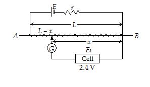
A battery of emf 4 V is connected across a 10 m long potentiometer wire having a resistance per unit length 1.6 W m–1. A cell of emf 2.4 V is connected so that its negative terminal is connected to the low potential end of the potentiometer wire and the other end is connected through a galvanometer to a sliding contact along the wire. It is found that the no-deflection point occurs against the balancing length of 8 m. Calculate the internal resistance of the 4 V battery.
Solution
emf of cell = (potential gradient) X (balancing length)
\displaystyle {{E}_{1}}=\frac{{{{V}_{{AB}}}}}{L}\times x
or \displaystyle 2.4=\frac{{{{V}_{{AB}}}}}{{10}}\times 8
⇒ VAB = 3 V
Consider the loop containing E. Applying potential divider concept,
\displaystyle {{V}_{{AB}}}=E\frac{{{{R}_{{AB}}}}}{{{{R}_{{AB}}}+r}}
⇒ \displaystyle 3=4\frac{{1.6\times 10}}{{1.6\times 10+r}}
⇒ r = 16/3 Ω
Note that as there is no current through the cell and galvanometer, the battery E, the internal resistance r and the potentiometer wire AB are in series.
Practice Questions (Basic Level)
Q.1
In an experiment to measure the internal resistance of a cell by a potentiometer, it is found that the balance point is at a length of 2 m, when the cell is shunted by a 5W resistance and at a length of 3 m, when the cell is shunted by a 10 W resistance. The internal resistance of the cell is
(a) 1.5 W (b) 10 W (c) 15 W (d) 1 W
Ans : (b)
Q.2
A resistance of 4W and a wire of length 5 metres and resistance 5W are joined in series and connected to a cell of e.m.f. 10V and internal resistance 1W. A parallel combination of two identical cells is balanced across 300 cm of the wire. The e.m.f. of each cell is
(a) 1.5 V
(b) 3.0 V
(c) 0.67 V
(d) 1.33 V
Ans. (b)
Practice Questions (JEE Main Level)
Q.1
If the length of the potentiometer wire is decreased, then its sensitivity :
(a) Increases
(b) Decreases
(c) Remains unaffected
(d) Either (b) or (c)
Ans: (b)
Q.2
In an experiment to measure the internal resistance of a cell by a potentiometer it is found that all the balance points at a length of 2 mtr. When the cell is shunted by a 5 ohm resistance, and is at a length of 3 m when the cell is shunted by a 10 ohm resistance, the internal resistance of the cell is then :
(a) 1.5 \displaystyle \Omega
(b) 10 \displaystyle \Omega
(c) 15 \displaystyle \Omega
(d) 1 \displaystyle \Omega
Ans: (b)
Q.3
A 10 m long wire of resistance 20 \displaystyle \Omega is connected in series with a battery of e.m.f. 3 V (negligible internal resistance) and a resistance of 10 \displaystyle \Omega . The potential gradient along the wire in volt per metre is :
(a) 0.02 (b) 0.1 (c) 0.2 (d) 1.2
Ans: (c)
Q.4
In a potentiometer experiment the balancing point with a cell is at length 240 cm. On shunting the cell with a resistance of 2 \displaystyle \Omega the balancing length becomes 120 cm. The internal resistance of the cell is :
(a) 1 \displaystyle \Omega
(b) 0.5 \displaystyle \Omega
(c) 4 \displaystyle \Omega
(d) 2 \displaystyle \Omega
Ans: (d)
Q.5
In the above question if the jockey touches the wire at a distance of 560 cm from A, what will be the current in the galvanometer ?
(a) \displaystyle \frac{{3E}}{{22r}}
(b) \displaystyle \frac{{13E}}{{22r}}
(c) \displaystyle \frac{{5E}}{{22r}}
(d) \displaystyle \frac{{7E}}{{24r}}
Ans : (a)
Q. 6
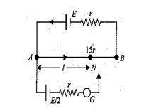
Consider the potentiometer circuit arranged as in fig. The potentiometer wire is 600 cm long, and its resistance is 15 r.
At what distance from point A should the jockey touch the wire to get zero deflection in the galvanometer ?
(a) 400cm
(b) 240 cm
(c) 320 cm
(d) 560cm
Ans. (c)
Practice Questions (JEE Advance Level)
Q.1
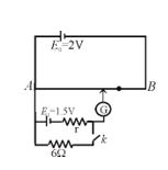
For the arrangement of the potentiometer shown in the figure, the balance point is obtained at a distance 75 cm from A when the key k is open. The second balance point is obtained at 60 cm from A when the key k is closed. Find the internal resistance (in W) of the battery E1.
Ans. 1.5 W
Q.2
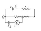
In the potentiometer circuit of given figure the galvanometer reveals a current in the direction shown wherever the sliding contact touches the wire. This can not be caused by
(a) E1 being too low
(b) r being too high
(c) a break in PQ
(d) E2 being too low
Ans. (d)
