Q.1
In the circuit shown if point O is earthed, the potential of point X is equal to
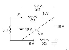
(a) 10 V
(b) 15 V
(c) 25 V
(d) 12.5 V
Ans. (b)
Q.2
The current in the arm CD in the circuit shown in the figure will be
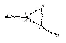
(a) {{i}_{1}}+{{i}_{2}}
(b) {{i}_{2}}+{{i}_{3}}
(c) {{i}_{1}}+{{i}_{3}}
(d) {{i}_{1}}-{{i}_{2}}+{{i}_{3}}
Ans. (b)
Q.3
In the given circuit, find the equivalent resistance between point A and B.

(a) 18 W
(b) 12 W
(c) 20 W
(d) 27 W
Ans. (b)
Q.4
In the given circuit diagram. Find the value of current in resistance R.
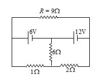
(a) 2 A
(b) \frac{3}{2}A
(c) 1 A
(d) 4 A
Ans : a
Q.5
The circuit as shown in figure. The ratio of current is
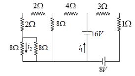
(a) 2
(b) 8
(c) 0.5
(d) 4
Ans. (b)
Q.6
In the given circuit the current i1 is
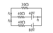
(a) 0.4 A
(b) –0.4 A
(c) 0.8 A
(d) –0.8 A
Ans. (b)
Q.7
The measurement of voltmeter (ideal) in the following circuit is
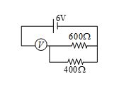
(a) 2.4 V
(b) zero
(c) 4.0 V
(d) 6.0 V
Ans. (d)
Q.8
If resistance of each wire in the network shown is r, the equivalent resistance between A & C is equal to
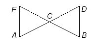
(a) r
(b) \frac{r}{2}
(c) \frac{{2r}}{3}
(d) \frac{{3r}}{2}
Q.9
Figure shows a network of a capacitor and resistors. The charge on capacitor in steady state is
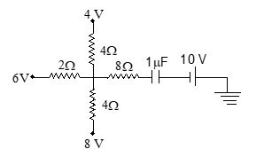
(a) 4 mC
(b) 6 mC
(c) 10 mC
(d) 16 mC
Ans. (d)
Q.10
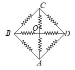
In the arrangement shown, the magnitude of each resistance is The equivalent resistance between O and A is given by
(a) \frac{{14}}{{15}}\Omega
(b) \frac{7}{{15}}\Omega
(c) \frac{4}{3}\Omega
(d) \frac{5}{6}\Omega
Ans. (a)
Q.11
Two cells with the same emf E and different internal resistances r1 and r2 are connected in series to an external resistance R. The value of R so that the potential difference across the first cell be zero is
(a) \sqrt{{{{r}_{1}}{{r}_{2}}}}
(b) {{r}_{1}}+{{r}_{2}}
(c) {{r}_{1}}-{{r}_{2}}
(d) \frac{{{{r}_{1}}+{{r}_{2}}}}{2}
Ans : (c)
Get Full Access Of the Chapters
