Lorem ipsum dolor sit amet, consectetur adipiscing elit. Ut elit tellus, luctus nec ullamcorper mattis, pulvinar dapibus leo.
1.
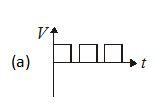
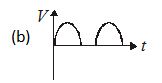
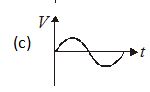
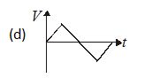
Which of the following represents the digital signal?
Ans (a)
2.
What is the process of superimposing signal frequency on the carrier frequency called?
(a) detection
(b) reception
(c) modulation
(d) transmission.
Ans (c)
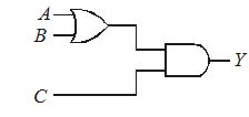
3.
To get an output Y = 1 from circuit in figure the input must be
A B C
(a) 0 1 0
(b) 1 0 0
(c) 1 0 1
(d) 1 1 0
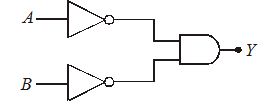
4.
What is the output Y of the gate circuit shown in the figure
(a) \bar{A}.\bar{B}
(b) \overline{\overline{{A.B}}}
(c) \overline{{A.B}}
(d) none of these.
Logic Gates (Basic Level)
1 / 10
Given below are symbols for some logic gates
The XOR gate and NOR gate respectively are
2 / 10
Given below are four logic gate symbol (figure). Those for OR, NOR and NAND are respectively
3 / 10
The following truth table corresponds to the logic gate
A 0 0 1 1
B 0 1 0 1
X 0 1 1 1
4 / 10
The combination of ‘NAND’ gates shown here under (figure) are equivalent to
5 / 10
A truth table is given below. Which of the following has this type of truth table
A 0 1 0 1
B 0 0 1 1
y 1 0 0 0
6 / 10
The truth table shown in figure is for
Y 1 0 0 1
7 / 10
For the given combination of gates, if the logic states of inputs A, B, C are as follows A = B = C = 0 and A = B = 1, C = 0 then the logic states of output D are
8 / 10
Boolean algebra is essentially based on
9 / 10
The logic behind ‘NOR’ gate is that it gives
10 / 10
A logic gate is an electronic circuit which
Your score is
The average score is 0%
Restart quiz
Get Full Access Of the Chapters